Hummer H1 (2006+). Manual - part 261
 

  Index      Hummer     Hummer H1 DMAX - service repair manual 2006 year


Search            


Content   ..  259  260  261  262   ..


Hummer H1 (2006+). Manual - part 261


9-22 Axles, Suspension and Frame

__________________________________________

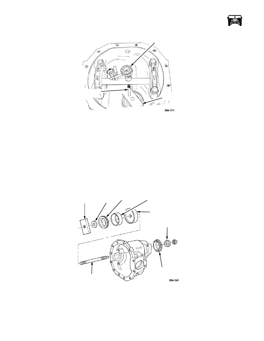
Figure 9-37:   Gauge Setting

13. After the zero setting is obtained, rotate the gauge shaft until the dial indicator plunger does not touch the gauge block.

14. Record the dial indicator reading. Example: If the pointer moved counterclockwise and stops between 0 and 11, add 100

inches to measurement for shim thickness. If the pointer moves counterclockwise and stops between 84 and 99, correct shim
thickness is indicated.

15. This reading indicates the shim thickness required for a pinion etched with a zero (0) on the pinion head. If the pinion being

installed has a plus (+) or minus (-) etching, then an adjustment of the shim thickness is required. Example: If a pinion is
etched +3, then 0.003 inches less shim thickness is required. Subtract 0.003 inches from the indicator reading. If a pinion is
etched -3, then 0.003 inches more shim thickness is required. Add 0.003 inches to the indicator reading.

16. Remove the dial indicator from the arbor (Figure  9-36).

17. Remove the four bolts, two bearing caps, discs and the arbor from the housing.

18. Remove the nut, pilot washer, front the pinion bearing and stud assembly from the housing (Figure  9-38).

Figure 9-38:   Pinion Front Bearing and Depth Tool Removal

19. Remove the gauge block, pilot washer, rear pinion bearing, rear pinion bearing cup and the gauge block from the stud.

20. Note the pinion depth variance marked on the pinion gear. If number is preceded by a plus (+) sign, add that amount in

thousands to the standard setting of 2.547 in. (6.46 cm). If the number is preceded by minus (-) sign, subtract that amount in
thousands from the standard setting of 2.547 in. (6.46 cm). The result of this addition or subtraction is the desired pinion depth.
Record for reference (Figure  9-39).

DIAL

INDICATOR

GAUGE

 BLOCK

INDICATOR

PLUNGER

GAUGE

BLOCK

PILOT

WASHER

RING PINION

BEARING CUP

GAUGE

BLOCK

FRONT PINION

BEARING

PILOT

WASHER

REAR PINION

BEARING

STUD

_________________________________________

 Axles, Suspension and Frame  9-23

Figure 9-39:   Pinion Depth Variance Number Location

21. Subtract the desired pinion depth (step 14) from the total measured pinion depth (step 15). Result of this subtraction is the

correct pinion depth shim thickness.

22. Lubricate the front pinion bearing and the pinion seal with gear oil. Using the yoke seal installer, to install the front pinion

bearing and the pinion seal in the housing (Figure  9-40).

Figure 9-40:   Pinion Seal Installation

23. Rotate the housing 180 degrees. Lubricate the outside diameter of the pinion rear bearing cup with gear oil (Figure  9-41).

PINION GEAR

PINION DEPTH

 VARIANCE NUMBER

SEAL INSTALLER J–38869

PINION FRONT

BEARING

HOUSING

PINION SEAL

9-24 Axles, Suspension and Frame

__________________________________________

NOTE:  If the pinion shim is beveled, be sure the beveled side faces the bottom of the bearing cup bore.

Figure 9-41:   Pinion Rear Bearing Installation

24. Using the driver handle J–8092 and the bearing cup installer J–8608, install the correct thickness pinion shim and the pinion

rear bearing cup in the housing.

25. Rotate the housing 90 degrees. Lubricate the rear pinion bearing with gear oil (Figure  9-42).

DRIVER

HANDLE

REAR PINION 

BEARING CUP 

INSTALLER

BEARING CUP

HOUSING

PINION SHIM

J–8092

TOOL J–8608

_________________________________________

 Axles, Suspension and Frame  9-25

Figure 9-42:   Rear Pinion Bearing Location

CAUTION:  Collapsible spacer controls the pinion bearing preload. Do not reuse the old spacer, or pinion bearing damage may
result.

26. Install the collapsible spacer on the pinion gear and install the pinion gear in the housing.

27. Install the pinion yoke on the pinion gear with the pinion nut.

CAUTION:  Do not exceed specified preload torque on pinion bearings. Do not loosen locknut to relieve the preload torque or
pinion bearing damage may result. If specified torque is exceeded, remove pinion gear and replace collapsible spacer and locknut
and adjust preload again.

28. Using tool J-8614-01 with bolt kit J-8614-5 to hold the pinion yoke, tighten the pinion nut only enough to remove the end play

and seat the pinion bearings in the housing. Rotate the pinion yoke while tightening to seat the bearings evenly.

29. Measure the torque required to rotate the pinion gear. The correct pinion bearing preload torque is 17-25 lb-in. (2-3 N•m) with

a new bearings and 10-15 lb-in. (1-2 N•m) with a used bearings.

30. Continue to tighten the pinion nut in small increments until the pinion bearing preload torque meets specifications.

31. Install the two side bearings on the differential assembly (Figure  9-43).

Figure 9-43:   Side Bearing Installation

NOTE:  Side bearing shims are available in thickness from 0.077-0.117 in. (1.96-2.97 mm) in increments of 0.001 in. (0.025 mm).

32. Rotate the housing downward 90 degrees. Install the side bearing cups and the side bearing shims on the side bearings. Use

0.080 in. (2 mm) shims as a starting point (Figure  9-44).

PINION REAR

BEARING

PINION GEAR

COLLAPSIBLE

HOUSING

PINION YOKE

PINION NUT

 SPACER 

SIDE BEARING

DIFFERENTIAL

ASSEMBLY

SIDE

BEARING


Content   ..  259  260  261  262   ..