Hummer H1 (2006+). Manual - part 249
8-12
Steering System
_____________________________________________________________
8.
Raise the steering column to the mounting bracket. Insert the thru-bolt, three washers, lockwasher, and the locknut. Finger
tighten the locknut.
9.
Slide the intermediate shaft yoke onto the splines while carefully aligning the scribe marks. Insert the bolt and tighten the
locknut to 60 lb-ft (81 N•m).
10. Tighten the thru-bolt and the locknut to 31 lb-ft (42 N•m).
11. Tighten the pivot bolt and the locknuts to 10 lb-ft (14 N•m).
12. Install the steering wheel.
13. Install the close-out panel.
14. Operate the vehicle to verify the steering wheel alignment.
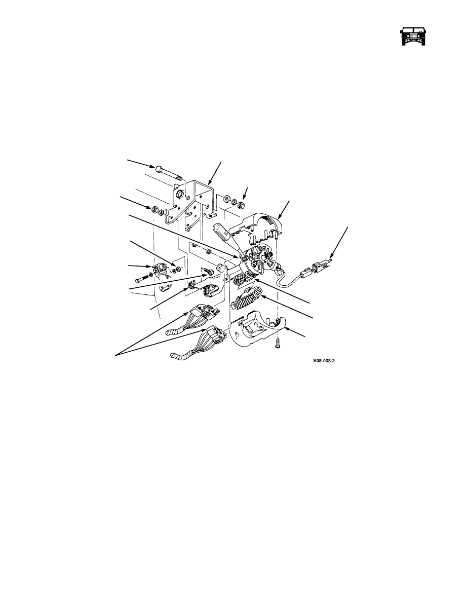
Figure 8-13: Steering Column Components
STEERING COLUMN MULTI-SWITCH REPLACEMENT
NOTE: This procedure covers the directional signal, horn, high beam, and hazard light switches.
Removal
1.
Remove the close-out panel.
2.
Remove the locknut, lockwasher, three washers, and the thru-bolt from the mounting bracket and loosen the pivot bolts. The
column will drop down as it pivots in the bracket (Figure 8-13).
3.
Remove the five screws and shroud (two halves) from the steering column.
4.
Disconnect the ground wires from the steering column.
5.
Remove the two screws and the multi-switch from the steering column (Figure 8-14).
6.
Remove the control handle from the multi-switch by pulling outward.
Installation
1.
Attach the control handle to the multi-switch (Figure 8-14).
2.
Secure the multi-switch to the steering column with the two screws.
3.
Connect the ground wires to the steering column.
7.
Secure the shroud (two halves) to the steering column with the five screws.
MOUNTING BRACKET
THRU-BOLT
SHROUD
IGNITION SWITCH
IGNITION SWITCH
SHROUD
MULTI-SWITCH
STEERING COLUMN
INTERMEDIATE SHAFT
60 lb-ft (81 N •m)
MULTI-SWITCH
10 lb-ft (14 N•m)
31 lb-ft (42 N•m)
CONNECTORS
CONNECTOR
LOCK CYLINDER
CONNECTOR
PIVOT BOLT
6-1-05