Hummer H1 (2006+). Manual - part 196
 

  Index      Hummer     Hummer H1 DMAX - service repair manual 2006 year


Search            


Content   ..  194  195  196  197   ..


Hummer H1 (2006+). Manual - part 196


5-24

Transmission/Transfer Case

_______________________________________________

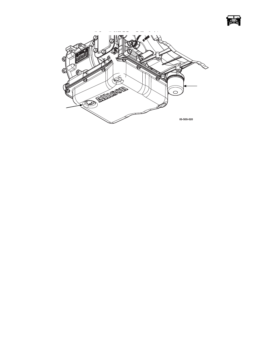
Figure 5-7:   Oil Filter And Drain Plug Location

FILL TUBE REPLACEMENT

Removal

1.

Remove the dipstick from the fill tube (Figure  5-8).

2.

Remove the two nuts securing the fill tube to the bell housing (Figure  5-8).

3.

Remove the bolt attaching the fill tube bracket to the intake manifold (Figure  5-8).

4.

Work the fill tube out of the transmission.

5.

Remove the fill tube seal from the transmission. Discard if damaged.

Installation

1.

Install the fill tube seal in the transmission.

2.

Push the fill tube into the transmission.

3.

Secure the fill tube to the bell housing using the two nuts.

4.

Secure the fill tube bracket to the intake manifold with the bolt. 

5.

Install the dipstick in the fill tube.

6.

Start the engine and top off the transmission fluid level if required.

OIL FILTER

DRAIN PLUG

_______________________________________________

 Transmission/Transfer Case  5-25

5745804

Figure 5-8:   Fill Tube Replacement

OIL PAN AND INTERNAL OIL FILTER REPLACEMENT 

1.

Raise the vehicle on a hoist.

2.

Remove the driveline protection.

3.

Remove the drain plug from the oil pan  and allow the fluid to drain into a suitable container.

4.

Remove the12 bolts that secure the oil pan to the transmission.

5.

Remove the oil pan and the gasket.

6.

Inspect the magnet for excessive metallic particles or large metallic particles that may indicate the need for an overhaul or
replacement of the transmission.

NOTE: DO NOT remove the transmission internal oil filter or seal if only replacing the oil pan or oil pan gasket.

FILL TUBE

FILL TUBE

SEAL

FILL TUBE TO

INTAKE BOLT

FILL TUBE TO

BELLHOUSING NUT

5-26

Transmission/Transfer Case

_______________________________________________

7.

Remove the transmission internal oil filter by pulling straight down where the suction tube is seated in the transmission case.

8.

Remove the transmission internal oil filter seal from the filter or from the seal bore in the transmission case. Discard the old
seal and the filter. 

Installation

1.

Remove all gasket material from the transmission case and the pan also remove any scratches from the transmission case that 
would cause a split line leak.

2.

Place a new seal on the tube of the transmission internal oil filter. Be sure the seal locates against the shoulder on the internal
oil filter tube.

3.

Push the filter and seal into the seal bore in the transmission case and position the transmission internal oil filter properly.

4.

Place a gasket on the oil pan and align the bolt holes.

5.

Hold the gasket and the oil pan in place while installing two bolts to hold the parts in place.

6.

Install the 10 remaining oil pan bolts and tighten the bolts to 20 lb-ft. (27 N•m).

7.

Install the drain plug and tighten the drain plug to 26 lb-ft. (35 N•m).

8.

Lower the vehicle.

9.

Fill the transmission with DEXRON

®

III Automatic Transmission Fluid and follow the fluid checking procedure.

VALVE BODY REPLACEMENT

Removal

1.

Disconnect the external wiring harness from the transmission main connector using J 44257 if the connector is not easily 
accessible.

2.

Remove the oil pan and transmission internal oil filter.

NOTE: The transmission main connector is actually one end of the internal harness that protrudes through the transmission case.

3.

Place a 30 mm (1 3/16 in) 12-point deep socket or box-end wrench over the connector.

4.

Push inward on the socket or wrench to release the retainer feet that attach the connector to the transmission case.

5.

Remove the wrench and push inward on the electrical connector to separate it from the transmission case. This allows the
internal wiring harness to remain with the control valve assembly when removed.

6.

Remove the two detent spring bolts and remove the detent spring assembly. 

NOTE: As the control valve assembly is removed, be careful not to lose the manual selector valve pin or allow the manual selector
valve to slide out of the control valve assembly.

7.

Remove the fifteen bolts securing the control valve assembly. 

8.

Support the control valve assembly, about 10 pounds, and remove the last bolt.

9.

Lower the control valve assembly to clear the locating pins in the transmission case.

10. Move the control valve assembly sideways to disengage the pin in the manual selector valve from the slot in the detent lever

and remove the control valve assembly (Figure  5-9).

_______________________________________________

 Transmission/Transfer Case  5-27

5745804

Figure 5-9:    Manual Selector Valve 

Installation 

1.

Move the control valve assembly into position under the transmission case. Engage the pin in the manual selector valve in the 
slot in the detent lever.

2.

Align the control valve assembly with the locating pins in the transmission case. Seat the control valve assembly against the
transmission case and hold in position.

3.

Install one bolt to hold the control valve assembly in place.

4.

Reinstall the remaining fifteen bolts that secure the control valve assembly to the transmission case and tighten the bolts to 108
in-lb (12 N·m).

5.

Push the transmission main connector outward through the hole in the transmission case until the retaining feet on the
connector are nearing the locked position and use J–44247 to complete the seating of the retaining feet that lock the connector
into the transmission case.

6.

Install the detent spring assembly onto the control valve assembly. Confirm that the roller of the detent spring assembly rests
on the detent lever.

7.

Install the two detent spring bolts and tighten the bolts to 108 in-lb (12 N·m).

8.

Install the oil pan and transmission internal oil filter.

9.

Connect the external wiring harness to the transmission main connector.

10. Fill the transmission with DEXRON

®

III Automatic Transmission Fluid and follow the fluid checking procedure.

CONTROL VALVE SOLENOID REPLACEMENT 

Removal

1.

Remove the oil pan and transmission internal oil filter.

2.

Disconnect the internal wiring harness from the solenoid being changed.

NOTE: For solenoid C, it may be necessary to remove the valve body to access the retaining clip (Figure  5-10).

3.

Remove the clip securing the solenoid and remove the solenoid (Figure  5-12).

NOTE: When the pressure control valve retaining bracket is removed, there are two sets of accumulators and springs which may
fall from the bores. Be sure to catch the accumulators and springs so as to prevent damage to these parts (Figure  5-11). 

CONTROL VALVE

ASSEMBLY

PIN

MANUAL

SELECTOR VALVE

DETENT LEVER


Content   ..  194  195  196  197   ..