Hummer H1 (2006+). Manual - part 195
 

  Index      Hummer     Hummer H1 DMAX - service repair manual 2006 year


Search            


Content   ..  193  194  195  196   ..


Hummer H1 (2006+). Manual - part 195


5-20

Transmission/Transfer Case

_______________________________________________

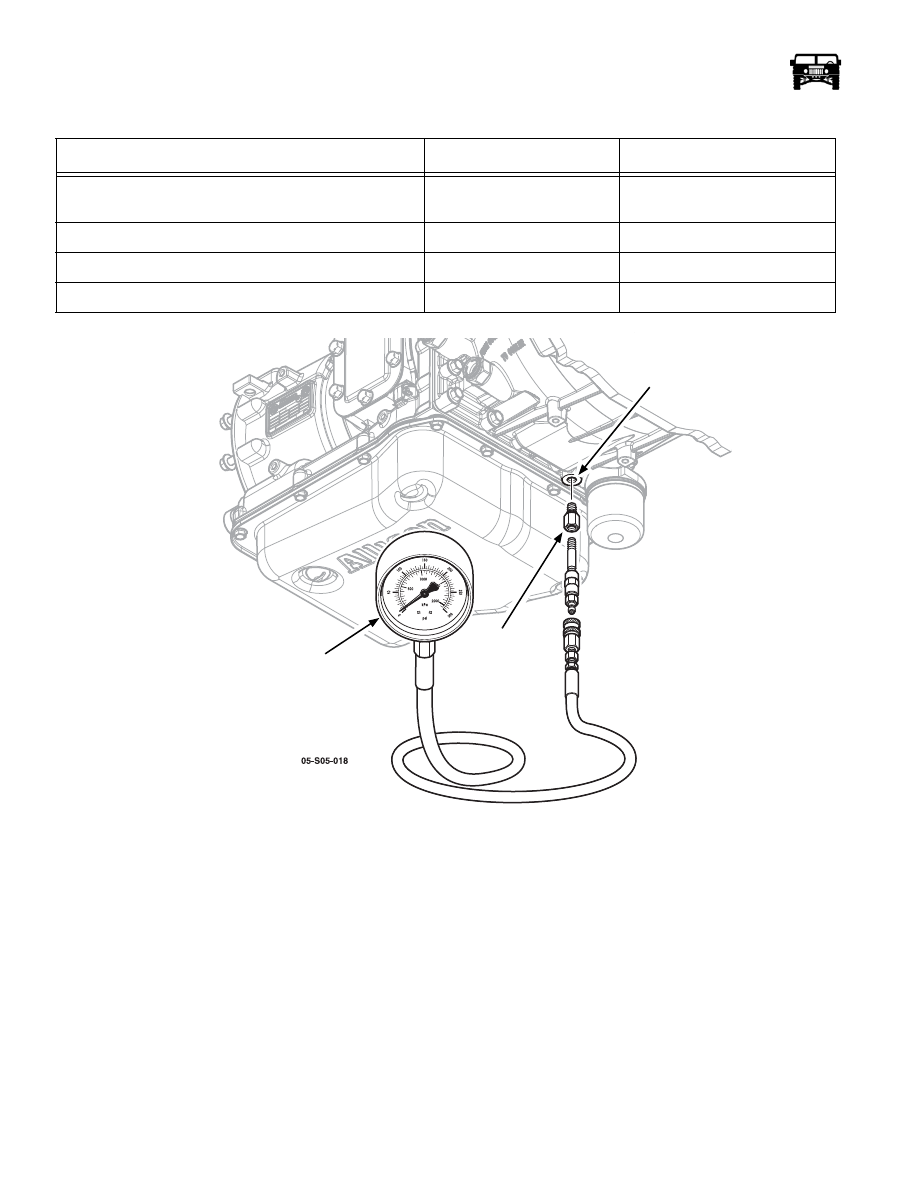
Figure 5-4:   Pressure Gauge

Transmission Warning Lamps

All the HUMMER H1 vehicles are equipped with malfunction indicator lights, a check engine, a check transmission and a check
throttle light. The purpose of the lights is to alert the driver when a transmission, engine, or electronic accelerator pedal circuit fault
has occurred.

The warning lights are in the circuit with the TCM, which controls light operation. The lights are illuminated for a few seconds at
startup as part of the bulb check and the circuit self test routine. The only other time illumination occurs, is when a system compo-
nent or circuit fault occurs.

 LINE PRESSURE CHART

Range 

Line Pressure @ 600 RPM 

Line Pressure @ 2100 RPM 

Forward Converter - Torque Converter Clutch Not 

Applied 

101-200 PSI (700-1,380 kPa) 

220-260 PSI (1,515-1,795 kPa) 

Forward Lockup - Torque Converter Clutch Applied 

N/A 

145-170 PSI (1,000-1,170 kPa) 

Reverse 

101-200 PSI (700-1,380 kPa) 

220-260 PSI (1,515-1,795 kPa) 

Neutral/Park 

85-105 PSI (590-720 kPa) 

220-260 PSI (1,515-1,795 kPa) 

TRANSMISSION

TEST PORT

PRESSURE

GAUGE

PRESSURE TEST

ADAPTER 

_______________________________________________

 Transmission/Transfer Case  5-21

5745804

TRANSMISSION CONTROL MODULE REPLACEMENT (TCM)

Removal

1.

Open the hood.

2.

Disconnect the batteries.

3.

Remove the electrical component cover to gain access to the ECM and the TCM (Figure  5-5).

4.

Remove the ECM and mounting bracket assembly (Figure  5-5).

5.

Remove the two TCM connectors.

6.

Remove the four retaining nuts securing the TCM to the TCM mounting bracket. 

Installation

1.

Secure the TCM to the TCM mounting bracket with the four retaining nuts.

2.

Plug the two connectors in to the TCM.

3.

Install the ECM and mounting bracket assembly.

4.

Install the electrical component cover.

5.

Reconnect the batteries.

6.

Close the hood.

7.

Program the new TCM using the tech 2.

8.

Perform the fast learn procedure.

5-22

Transmission/Transfer Case

_______________________________________________

Figure 5-5:   Transmission Control Module (TCM)

ELECTRICAL

COMPONENT

COVER

ENGINE CONTROL

TRANSMISSION CONTROL

MODULE (ECM)

ECM MOUNTING

BRACKET

MODULE (TCM)

TCM MOUNTING

BRACKET

_______________________________________________

 Transmission/Transfer Case  5-23

5745804

TRANSMISSION COOLER FLUSHING AND FLOW TESTING PROCEDURE

1.

Raise the vehicle on a hoist.

2.

Remove the P clamps (Figure  5-6).

3.

Remove the two bolts securing the bypass valve to the frame rail (Figure  5-6).

4.

Disconnect the transmission cooler lines from the transmission (Figure  5-6).

5.

Disconnect the transmission cooler lines going from the bypass valve to the cooler at the bypass valve (Figure  5-6).

6.

Remove the bypass valve and the cooler lines to the transmission as an assembly.

7.

Remove the thermal valve by un threading it from the bypass valve.

8.

Flush the bypass valve and attached lines with a parts washer. 

9.

Connect the flusher adapters J-44835 to the cooler lines at the adapter connections (Figure  5-6).

10. Using the trans flow transmission cooling system service tool J-45096, follow the procedure outlined on the front of the

service tool for Setup, and Flow Test Flush Procedure.

Figure 5-6:   Transmission Cooler lines

Transmission Fluid and External Oil Filter Replacement

1.

Position an proved waste oil container under the vehicle and remove the drain plug (Figure  5-7).

2.

Loosen the spin off filter by turning it counter clockwise (Figure  5-7).

3.

Remove the filter and replace it with a new filter.

4.

Install and tighten the drain plug.

5.

Refill the transmission with Dexron III fluid.

6.

The transmission refill capacity (after filter change) is approximately 8.5 qts. (8.0 L). 

7.

Refer to the proper fluid checking procedure.

P CLAMPS

BYPASS VALVE

COOLER RETURN

LINE

FLOW TO 

THE COOLER

ADAPTER

CONNECTIONS

THERMAL

VALVE


Content   ..  193  194  195  196   ..