Hummer H1 (2002+). Manual - part 94
___________________________________________
Transmission/Transfer Case 5-175
®
05745159
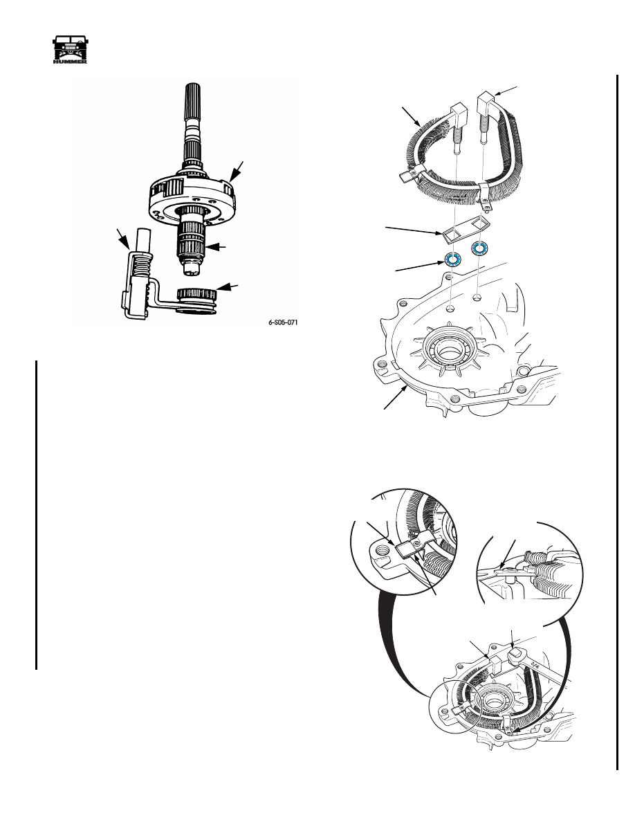
Figure 5-149: Mode Fork and Sleeve Installation
19. Install detent plunger, spring, and plug. Replace O-ring on
plug before hand and tighten plug to 12-18 lb-ft (16-24
N•m) (Figure 5-154).
20. Install range lever on sector shaft, then secure lever with
washer and nut (Figure 5-154). Tighten nut to 20-25 lb-ft
(27-34 N•m).
21. Install shift sector shaft O-ring and nylon bushing. Use
thin wall socket to seat O-ring and bushing.
22. Install support bracket onto oil cooler, then install sealing
washers, set oil cooler into the transfer case front half and
install external hardware. Hand tighten only.
(Figure 5-150)
23. Align the upper support tab in the recess of the case and
ensure that the lower tab, the one with the extra rivet
installed, rests on the recessed casting. The lower tab is
designed to have the rivet compressed between the
recessed casting area of the front and rear transfer case
halves when the halves are bolted together. Make sure that
the tabs do not intrude into the machined mating surface
area of the transfer case halves. Do not bend the cooler
when moving into position, damage to the manifold area
could occur from induced stress.While gently holding the
cooler with a 3/4" wrench on the manifold, tighten
hardware to 15 lb-ft. (Figure 5-151)
NOTE:
If the cooler is tightened incorrectly, the tension
placed on the cooler assembly could cause cracking, leaking
and loss of transmission fluid into the transfer case assembly.
Figure 5-150: Transfer Case Cooler Support Bracket
Installation
Figure 5-151: Transfer Case Cooler Support Tabs
DIFFERENTIAL
MAINSHAFT
MODE
SLEEVE
MODE FORK
ASSEMBLY
9-S05-003.1
COOLER SUPPORT
BRACKET
COOLER SEALING
WASHERS
TRANSFER CASE
OIL COOLER
TRANSFER CASE
FRONT HALF
MANIFOLD
9-S05-002.2
CASE HALF
RECESS
HOLD WHEN
TIGHTENING
HARDWARE
UPPER COOLER
SUPPORT TAB
TIGHTEN
FIRST
LOWER
SUPPORT
TAB
4-1-00