Hummer H1 (2002+). Manual - part 22


  Index      Hummer     Hummer H1 - service repair manual 2002 year


Search            


Content   ..  20  21  22  23   ..


Hummer H1 (2002+). Manual - part 22


____________________________________________________________________


 Engine  2-49


®


05745159

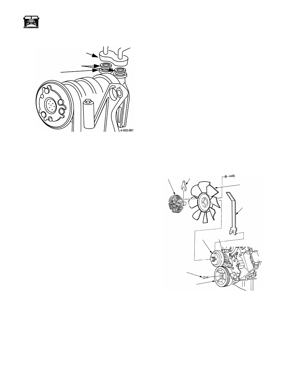
19. Remove protective tape from A/C suction/discharge hose

adapter and connect it to compressor. Install new seal washers.


Figure 2-61:   Suction/Discharge Hose Connection


20. Connect glow relay cable and wires.

21. Position support on back of alternator. Then install gen-

erator, mounting bracket, idler pulley, support, and tensioner
assembly.

22. Position remaining cables for battery installation.

23. Connect heater hoses to water pump and water crossover.

Mount idler pulley on generator bracket.

24. Install fan and clutch assembly.

25. Install serpentine belt.

26. Connect air inlet hose to turbocharger.

27. Attach radiator upper hoses and tube to thermostat

housing.

28. Connect battery positive cable and solenoid wire to starter

motor. 

29. Position radiator, shroud, condenser, and oil cooler

assembly on frame and between air lift brackets, with aid
of helper. Then secure assembly and supports to frame and
air lift brackets. Tighten support bolts to 26 lb-ft (35 N•m)
torque. Tighten frame mount bracket bolt to 30 lb-ft (41
N•m) torque.


NOTE: 


Verify that fan-to-shroud clearance is at least 1/4 inch

(3.18 mm) at all points around shroud before proceeding.
Loosen bolts and adjust position if necessary.

30. Connect radiator upper and lower hoses.

31. Connect surge tank hose to radiator.

32. Install return lines onto power steering pump.

33. Connect power steering pump return lines to oil cooler.

34. Remove protective wrapping or caps and connect hoses to

A/C condenser and oil coolers. Use new O-rings on cooler
and A/C hoses (Figure 2-61).

35. Install passenger and driver side splash shields.

36. Install battery tray and batteries. Connect positive and

negative cables to batteries.

37. Install seals and cover plates on air lift brackets. Notched

side of seals face engine.

38. Refill engine cooling system, refill engine crankcase with

recommended oil, and top off transmission and power
steering fluids.

39. Evacuate A/C system for 30 minutes, and recharge. 

40. Leakcheck A/C system.

41. Start and run engine. Bleed injectors at line fittings if

necessary. Then stop engine, recheck coolant and lubricant
levels, and add as necessary.

42. Bleed cooling system with air bleeds on engine and

radiator.

43. Test drive vehicle and check for leaks or vibrations.


ENGINE DISASSEMBLY

Serpentine Belt Removal


1.

Rotate belt tensioner counterclockwise with 1/2 in. drive 
breaker bar.

2.

Slide belt off tensioner pulley and remove belt.


Figure 2-62:   Fan and Pulley Removal

HOSE ADAPTER

COMPRESSOR

PORTS

SEAL 

WASHERS

CLUTCH

FAN

PUMP WATER

PUMP

CRANKSHAFT PULLEY

PULLEY BOLT (4)

PULLEY

SPANNER

WRENCH

7-S02-017.2


2-50

Engine


_____________________________________________________________________


®


Fan and Pulley Removal


1.

Insert spanner J–41240-1 in holes in water pump pulley 
(Figure 2-62).

2.

Use spanner to hold water pump shaft and wrench J–
41240-5A to loosen nut securing fan clutch to water pump.

3.

Remove bolts attaching fan to fan clutch.

4.

Remove fan and clutch from water pump.

5.

Remove crankshaft pulley attaching bolts and remove
pulley  (Figure 2-62).

6.

Remove torsional damper bolt with socket and impact
wrench. Retain damper bolt and washer.

7.

Loosen torsional damper with tool J–23523-F  (Figure 2-63).

8.

Remove damper and woodruff keys from crankshaft.


Figure 2-63:   Torsional Damper Removal

Figure 2-64:   Torsional Damper Attachment


Alternator and Bracket Removal


1.

Remove alternator mounting bolts and remove alternator.

2.

Remove alternator mounting and support bracket bolts and
remove both brackets  (Figure 2-65).

3.

Remove filler neck strap bolts and remove filler neck if
desired  (Figure 2-65).


Figure 2-65:   Alternator and Bracket Removal


A/C Compressor Removal


1.

Remove A/C compressor braces.

2.

Remove bolts/nuts attaching compressor to mounting
bracket and remove compressor  (Figure 2-66).


Figure 2-66:   A/C Compressor Removal

DAMPER

TOOL J–23523-F

KEY

DAMPER

BOLT AND

WASHER

CRANKSHAFT

ALTERNATOR

OIL FILLER NECK

MOUNTING BRACKET AND PULLEYS

REAR 

BRACKET

SUPPORT

A/C 

ENGINE 

COMPRESSOR

BRACKET


____________________________________________________________________


 Engine  2-51


®


05745159


Power Steering Pump and Bracket Removal


1.

Remove bolts/nuts attaching pump mounting bracket to 
block and cylinder head and remove pump and bracket as 
assembly.

2.

If pump requires service, remove pump attaching bolts and
remove pump from bracket (Figure 2-67).


Figure 2-67:   Power Steering Pump and Bracket Removal.


Exhaust Manifold Removal


1.

Loosen turbocharger left side inlet pipe flange clamps.

2.

Remove left side inlet pipe.

3.

Remove left side manifold attaching bolts and remove
manifold and gasket. Discard gasket  (Figure 2-68).

4.

Loosen turbocharger right side inlet pipe flange clamps.

5.

Remove right side manifold bolts and remove manifold
and gasket. Discard gasket  (Figure 2-69).

6.

Remove inlet tube.


Figure 2-68:   Left Side Exhaust Manifold Removal 

Figure 2-69:   Right Side Exhaust Manifold Removal.

MOUNTING BRACKET

PUMP PULLEY

POWER

STEERING

PUMP

SUPPORT BRACKET

SHIELD

DRIVER SIDE

EXHAUST MANIFOLD

MANIFOLD BOLT (TYPICAL)

PIPE

CLAMP

PASSENGER SIDE

EXHAUST MANIFOLD


2-52

Engine


_____________________________________________________________________


®


Intake Manifold Removal 


1.

Remove bolts and studs attaching each manifold half to 
cylinder head.

2.

Tap each manifold half with rawhide mallet to loosen it.

3.

Lift and remove manifold halves and gaskets  (Figures 2-70
and 2-71). Discard gaskets.


Figure 2-70:   Left Side Intake Manifolds Removal/

Installation 

Figure 2-71:   Right Side Intake Manifold 

Removal/Installation


Turbocharger and Center Manifold 
Removal


1.

Remove turbocharger inlet and outlet pipes.

2.

Remove bolts attaching turbocharger to engine.

3.

Remove bolts attaching vacuum actuator to turbocharger
and engine block.

4.

Remove turbocharger and actuator.

5.

Remove center manifold and gaskets (Figure 2-72).


Figure 2-72:   Center Manifold 


Water Crossover Removal


1.

Loosen clamp and disconnect bypass hose at water cross-
over  (Figures 2-73 and 2-74).


Figure 2-73:   Water Crossover Location 


2.

Remove crossover attaching bolts/studs and remove
crossover. Discard crossover gaskets  (Figure 2-74).

3.

Remove thermostat housing and thermostats if required.
Note that turbo diesel has two thermostats  (Figure 2-74).


.


Figure 2-74:   Water Crossover Mounting

GASKET

INTAKE MANIFOLD

HALF 

GASKET

INTAKE MANIFOLD HALF

GASKET

O-RING

GASKET

TURBOCHARGER

CENTER

MANIFOLD

DUAL  THERMOSTAT

COVER

WATER CROSSOVER

CROSSING

THERMOSTAT

TWIN 

GASKETS

WATER

 CROSSOVER

THERMOSTATS

 HOUSING


Content   ..  20  21  22  23   ..