Hummer H1 (1992-1998). Manual - part 14
Change 1
2-45
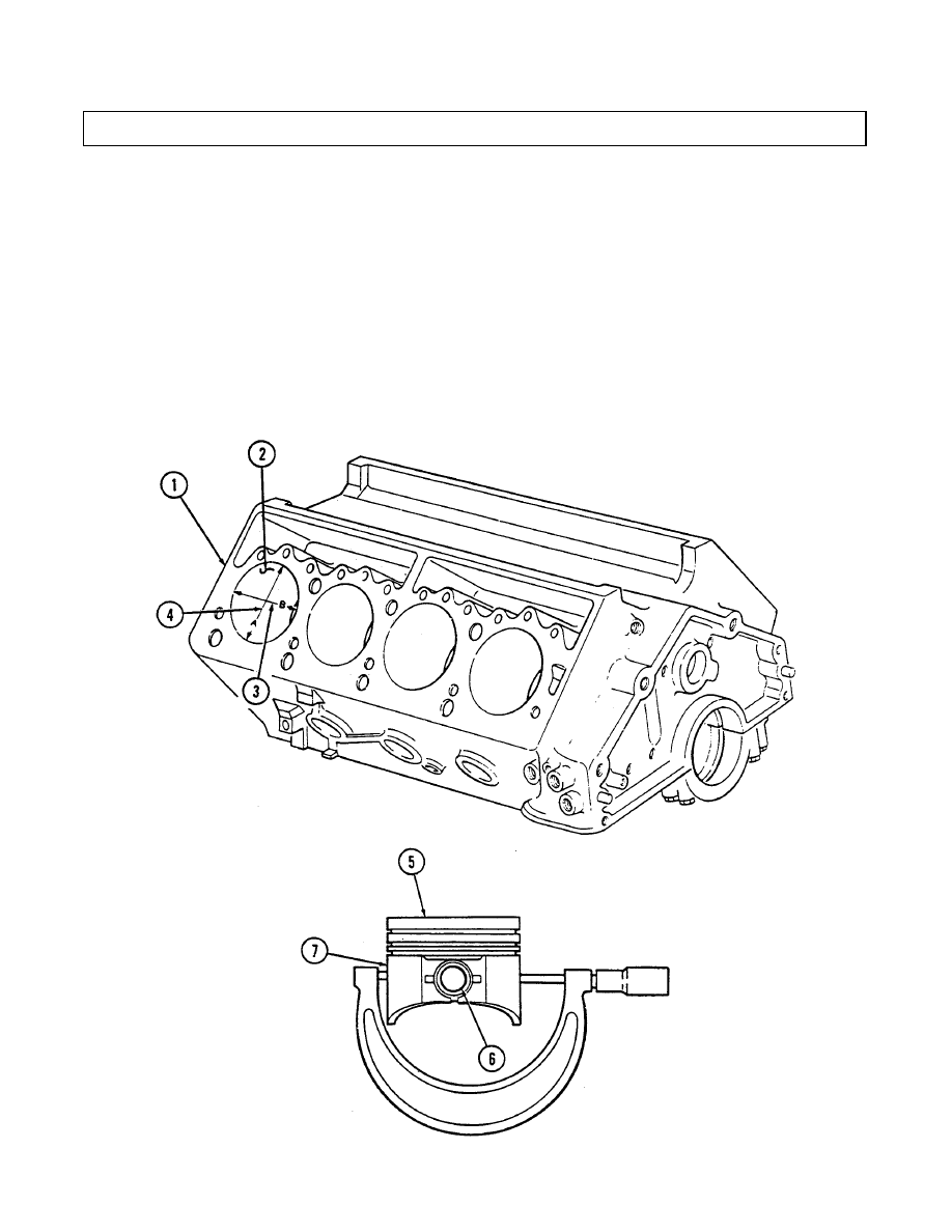
2 - 1 6 . CYLINDER BLOCK REPAIR (Cont‘d)
NOT E
Occasionally during the honing operation, cylinder bore should be
thoroughly cleaned, and the piston-to-bore clearance checked for correct fit.
f.
Using cylinder hone, refinish cylinder bore (2). Hone should be moved up and down at sufficient
speed to obtain very fine uniform surface finish marks, in a cross-hatch pattern of approximately
45° to 65° included angle. The finish marks should be clean, not sharp, and free from imbedded
particles and torn or folded material.
g. If a “Hi-Limit” piston or oversized piston (5) was fitted to a cylinder bore (2), permanently mark
the piston (5) for the cylinder bore (2) to which it has been fitted.
h. Repeat steps f. and g. for remaining cylinder bores.
i.
Thoroughly clean the cylinder block (1) with hot water and detergent. Scrub cylinder bores (2)
with a stiff brush and rinse thoroughly with hot water. The cylinder bores (2) should be coated
with OE/HDO and wiped with a clean, dry cloth.