Hummer H1 (1992-1998). Manual - part 13
 

  Index      Hummer     Hummer H1 - service repair manual 1992-1998 year


Search            


Content   ..  11  12  13  14   ..


Hummer H1 (1992-1998). Manual - part 13


2-16. CYLINDER BLOCK REPAIR (Cont’d)

WARNING

Compressed air used for cleaning purposes will not exceed 30 psi
(207 kPa). Use only with effective chip guarding and personal
protective equipment (goggles/shield, gloves, etc.).

d. Blow all dirt and cleaning solution from capscrew holes and oil passages with compressed air.
e. Refer to para. 2-9 for additional cleaning instructions.
f. Coat all cylinder bores, lifter bores, and machined surfaces with OE/HDO.

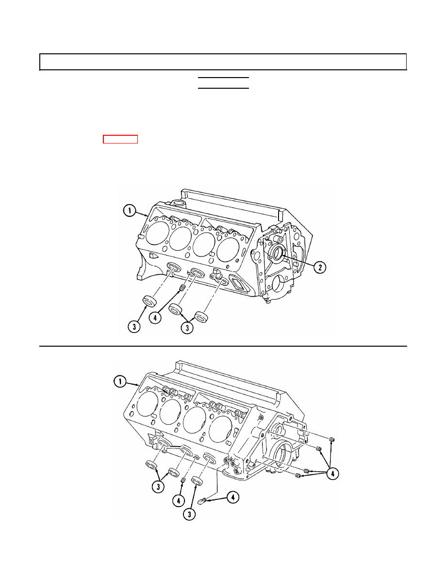
g. Apply pipe sealing compound to six protective dust caps (3) and all plugs (4) and install in

cylinder block (1).

2-41

2-42          Change 1

2 - 1 6 . CYLINDER BLOCK REPAIR (Cont‘d)

2.

Steam cleaning.
a. Remove six protective dust caps (9) and all plugs (10) from cylinder block (1).

WARNING

When steam cleaning, protective clothing must be used. Failure to
use protective clothing may result in serious injury.

b. Thoroughly steam clean cylinder block (1).
c. Run rods with brushes through all oil passages and repeat step b.

WARNING

Compressed air used for cleaning purposes will not exceed 30 psi
(207 kPa). Use only with effective chip guarding and personnel
protective equipment (goggles/shield, gloves, etc.).

d. Blow all dirt and cleaning solution from capscrew holes and oil passages with compressed air.
e. Refer to para. 2-9 for additional cleaning instructions.
f.

Coat all cylinder bores, lifter bores, and machined surfaces with OE/HDO.

g. Apply pipe sealing compound to six protective dust caps (9) and all plugs (10) and install in

cylinder block (1).

c. Inspection

NOTE

• For general inspection instructions, refer to para. 2-10.
• If cylinder block inspection indicates that cylinder block is

suitable for continued use, except for out-of-round, taper, or
minor nicks or scratches, it can be conditioned by honing or
boring.  The cylinder block can then be fitted with a Hi-Limit or
oversized piston (refer to para. 2-45, table 2-4 or 2-5). The 6.5L
engines do not have Hi-Limit pistons.

1.

Inspect all surfaces and general overall condition of the cylinder block (1).

2.

Visually check the cylinder block (1) for pitting in cylinder walls (4) and lifter bores (2). Replace
engine if pitted or distorted.

3.

Inspect the cylinder block (1) for cracks in cylinder walls (4), water jacket (5), lifter bores (2), and
main bearing webs (8). Replace engine if cracked.

4.

Inspect main bearing caps (6) for cracks, scoring, or damage. Replace engine if any are cracked,
scored, or damaged.

5.

Inspect main bearing cap bolts (7) for damage. Replace if damaged.

6.

Inspect dowel pins (3) for damage. Replace if damaged.

7.

Using a straightedge and feeler gauge, check flatness of cylinder head sealing surfaces on cylinder
block (1). Flatness on cylinder block (1) must not vary more than 0.002 in. (0.051 mm) in a distance
of 6 in. (15.2 mm) or more than 0.006 in. (0.152 mm) overall. Repair cylinder or replace engine if
flatness does not meet above specifications.

NOTE

Perform step 7.1 for 1997 6.5L engines only.

7.1.

Inspect piston oil nozzles (11) and bores (12) for damage. Replace piston oil nozzles (11) if damaged.

Change 1

2-43

2 - 1 6 . CYLINDER BLOCK REPAIR (Cont‘d)

2-44          Change 1

2 - 1 6 . CYLINDER BLOCK REPAIR (Cont‘d)

d. Repair

1.

Boring.
a. Before using any type of boring bar, the top of the cylinder block should be filed off to remove

any dirt or burrs.  This is very important.  If not checked, the boring bar may be tilted, which
would result in the rebored cylinder wall not being at right angles to the crankshaft.

b. Measure piston diameter of the piston to be used at the skirt across the center line of the piston pin.
c. Using a boring bar, bore the cylinder to the same diameter as the piston.  Hone the cylinder to

get proper piston-to-bore clearance.

d. Repeat steps b. and c. for remaining cylinders.

2.

Honing.
a. Using cylinder bore gauge, measure cylinder bore (2) for cylinder bore diameter. Measurement

must be taken at point “A” (4) 2-1/2 in. (64 mm) from top of cylinder bore (2).

b. Measure “piston diameter” of piston (5) removed from corresponding cylinder using a micro-

meter at piston skirt (7) across center line of piston pin (6).

c. Subtract “piston diameter” from “cylinder bore diameter” to determine “piston-to-bore

clearance”.

d. Repeat steps a. through c. for remaining cylinder bores and pistons.

NOT E

• Cylinders can be conditioned with a hone or boring bar and fitted with a

standard “Hi-Limit” piston or oversized piston, if necessary.

• If a cylinder is pitted or worn such that it cannot be honed and fitted with

a “Hi-Limit” piston or oversized piston, a cylinder sleeve may be used to
repair the engine block.

• 6.5L engines do not have “Hi-Limit” pistons.

e. If all cylinder bores (2) have proper “piston-to-bore clearance” of 0.004-0.005 in. (0.102-0.127 mm)

or if proper “piston-to-bore clearance” may be obtained using a standard “Hi-Limit” piston or
oversized piston, go to step f. If not, engine may be repaired using a cylinder sleeve (para. 2-16.d.2).

NOT E

If cylinder bores are found to have less than 0.005 in. (0.127 mm) wear,
taper, or out-of-round, they may be honed oversize (refer to para. 2-16.d.1)
and fitted with “Hi-Limit” standard size pistons.

8.

Using cylinder bore gauge, measure all cylinder bores (2) for taper. Measurements must be taken
at point “A” (4) at top and bottom of cylinder bore (2). If any cylinder exceeds specifications 
(table 2-2 or 2-3) by 0.005 in. (0.127 mm) or more, repair cylinder or replace engine.

9.

Using cylinder bore gauge, measure all cylinder bores (2) for out-of-round. Measurement must be
taken at point “A” (4) and point “B” (3) at top and bottom of cylinder bore (2). If any cylinder exceeds
specifications (table 2-2 or 2-3) by 0.005 in. (0.127 mm) or more, repair cylinder or replace engine.

10.

Using cylinder bore gauge, measure all cylinder bores (2) for bore diameter. Measurement must be
taken at point “A” (4) 2-1/2 in. (64 mm) from top of cylinder bore (2). If any cylinder exceeds
specifications (table 2-2 or 2-3) by 0.005 in. (0.127 mm) or more, repair cylinder or replace engine.

NOT E

If cylinder block inspection indicated that the cylinder block was suitable
for continued use except for out-of-round, taper, or minor nicks or
scratches, it can be conditioned by honing or boring.


Content   ..  11  12  13  14   ..