Honda Odyssey (2024 year). Manual in english - page 20
 

  Index      Manuals     Honda Odyssey (2024 year). Manual in english


Search            copyright infringement  


Content      ..     18      19      20     


Honda Odyssey (2024 year). Manual in english - page 20


Continued

643

uu

If a Tire Goes Flat

u

Changing a Flat Tire

Han

d

lin
g the U

n

expected

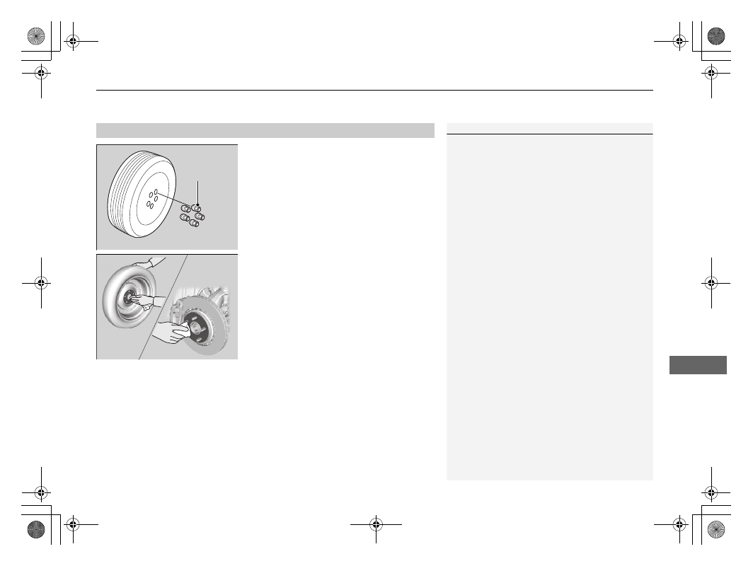
1.

Remove the wheel nuts and flat tire.

2.

Wipe the mounting surfaces of the wheel 
with a clean cloth.

3.

Mount the compact spare tire.

4.

Screw the wheel nuts until they touch the 
lips around the mounting holes, then stop 
rotating.

Replacing the Flat Tire

1

Replacing the Flat Tire

Do not over tighten the wheel nuts by applying extra 
torque using your foot or a pipe.

Wheel 
Nut

uu

If a Tire Goes Flat

u

Changing a Flat Tire

644

Han

d

lin
g the U

n

expected

5.

Lower the vehicle and remove the jack. 
Tighten the wheel nuts in the order 
indicated in the image. Go around 
tightening the nuts two to three times in 
this order.

Wheel nut torque:

94 lbf∙ft (127 N∙m, 13 kgf∙m)

The tire storage bag, bracket, mounting wing 
bolt (A) and mounting wing bolt (B) are in the 
tool case.

1.

Put the flat tire in the tire storage bag 
provided with your vehicle.

Storing the Flat Tire

1

Storing the Flat Tire

3

WARNING

Loose items can fly around the interior in a 
crash and can seriously injure the 
occupants. 
Store the wheel, jack, and tools securely 
before driving.

Bracket

Mounting Wing Bolt (A)

Mounting Wing Bolt (B)

Tire Storage Bag

645

uu

If a Tire Goes Flat

u

Changing a Flat Tire

Continued

Han

d

lin
g the U

n

expected

2.

Pull down the U-shaped carpet piece.

3.

Remove the plastic screw with a coin.

4.

Install the bracket and the mounting wing 
bolt (A) on the attachment point, and 
tighten the bolt.

5.

Install the flat tire on the bracket with the 
inside of the wheel facing toward you.

6.

Install the mounting wing bolt (B) to the 
bracket through one of the five wheel nut 
holes, and tighten the bolt.

u

Poke a hole in the storage bag as 
needed.

Plastic Screw

Carpet Piece

Mounting 
Wing Bolt 
(A)

Bracket

Mounting Wing Bolt (B)

646

uu

If a Tire Goes Flat

u

Changing a Flat Tire

Han

d

lin
g the U

n

expected

Storing a flat tire on the folded third row seat

1.

Turn over the flap on the left side of the 
cargo area floor.

2.

Pull down the U-shaped carpet piece and 
remove the plastic screw with a coin.

3.

Place the flat tire face down on the 
attachment point.

4.

Put the tire mounting wing bolt (B) in the 
attachment point through one of the five 
wheel nut holes, and tighten the bolt.

u

Poke a hole in the storage bag as 
needed.

Plastic Screw

Mounting 
Wing Bolt 
(B)

647

uu

If a Tire Goes Flat

u

Changing a Flat Tire

Han

d

lin
g the U

n

expected

If you replace a flat tire with the compact spare tire, the low tire pressure/TPMS 
indicator comes on while you are driving. After driving for a few miles (kilometers), 

Tire Pressure Monitor Problem

 will appear on the driver information interface 

and the indicator will start blinking for a short time and then stay on; however, this 
is normal and is no cause for concern.

If you replace the tire with a regular tire, the warning message on the driver 
information interface and the low tire pressure/TPMS indicator will go off after a few 
miles (kilometers).

TPMS with Tire Fill Assist and the Compact Spare Tire

1

TPMS with Tire Fill Assist and the Compact Spare Tire

The system cannot monitor the pressure of the 
compact spare tire. Manually check the compact 
spare tire pressure to be sure that it is correct.

Use the TPMS specific wheels. Each is equipped with 
a tire pressure sensor mounted inside the tire behind 
the valve stem.

648

Han

d

lin
g the U

n

expected

Engine Does Not Start

Checking the Engine

If the engine does not start, check the starter.

If you cannot start the engine after checking all the items in the list above, have your vehicle checked by a dealer.

If you must start the vehicle immediately, use an assisting vehicle or booster battery to jump start it.

2

If the Battery Is Dead

 P. 651

Starter condition

Checklist

Starter doesn’t turn or turns 
over slowly.

The battery may be dead. Check 
each of the items on the right and 
respond accordingly.

Check for a message on the driver information interface.

If the 

To Start, Hold Remote Near Start Button

 message appears

2

If the Remote Battery is Weak P.

649

u

Make sure the remote is in its operating range.

2

ENGINE START/STOP Button Operating Range

 P. 188

Check the fuses.

Check all fuses, or have your vehicle checked by a dealer.

2

Inspecting and Changing Fuses

 P. 668

The starter turns over normally 
but the engine doesn’t start.

There may be a problem with a 
fuse. Check each of the items on 
the right and respond accordingly.

Review the engine start procedure.

Follow its instructions, and try to start the engine again.

2

 Starting the Engine

 P. 470

Check the immobilizer system indicator.

When the immobilizer system indicator is blinking, the engine cannot be started.

2

Immobilizer System

 P. 181

2

Immobilizer System Indicator

 P. 98

Check the fuel level.

There should be enough fuel in the tank.

2

 Fuel Gauge

 P. 126

Check the fuses.

Check all fuses, or have your vehicle checked by a dealer.

2

Inspecting and Changing Fuses

 P. 668

If the problem continues:

2

Emergency Towing

 P. 669

649

uu

Engine Does Not Start

u

If the Remote Battery is Weak

Han

d

lin
g the U

n

expected

If the Remote Battery is Weak

If the beeper sounds, the 

To Start, Hold Remote Near Start Button

 message 

appears on the driver information interface, the 

ENGINE START/STOP

 button 

flashes, and the engine won’t start, start the engine as follows:

1.

Press the 

ENGINE START/STOP

 button.

u

The beeper sounds and the 

ENGINE 

START/STOP

 button flashes for about 

30 seconds.

2.

Touch the center of the 

ENGINE START/

STOP

 button with the 

H

 logo on the keyless 

remote while the 

ENGINE START/STOP


button is flashing. The buttons on the 
keyless remote should be facing you.

u

The beeper sounds, and the 

ENGINE 

START/STOP

 button stays on for about 

10 seconds.

3.

Depress the brake pedal and press the 

ENGINE START/STOP

 button while the 

ENGINE START/STOP

 button is on.

u

The engine starts.

u

If you don’t depress the pedal, the mode 
will change to ACCESSORY.

650

uu

Engine Does Not Start

u

Emergency Engine Stop

Han

d

lin
g the U

n

expected

Emergency Engine Stop

The 

ENGINE START/STOP

 button may be used to stop the engine due to an 

emergency situation even while driving. If you must stop the engine, do either of the 
following operations:

Press and hold the 

ENGINE START/STOP

 button for about two seconds.

Firmly press the 

ENGINE START/STOP

 button three times.

The steering wheel will not lock. However, because turning off the engine disables 
the power assist the engine provides to the steering and braking systems, it will 
require significantly more physical effort and time to steer and slow the vehicle. Use 
both feet on the brake pedal to slow down the vehicle and stop immediately in a 
safe place.

The gear position automatically changes to 

(

P

 after the vehicle comes to a complete 

stop.

Then, the power mode changes to VEHICLE OFF.

Then, press the 

ENGINE START/STOP

 button twice without depressing the brake 

pedal to change the mode to VEHICLE OFF.

1

Emergency Engine Stop

NOTICE

Do not press the 

ENGINE START/STOP

 button while 

driving unless it is absolutely necessary for the engine 
to be turned off.
If you press the 

ENGINE START/STOP

 button while 

driving, the beeper sounds.

U.S. models

Canadian models

651

Continued

Han

d

lin
g the U

n

expected

If the Battery Is Dead

Jump Starting Procedure

Turn off the power to electric devices, such as audio and lights. Turn off the engine, 
then open the hood.

1.

Connect the first jumper cable to your 
vehicle’s battery 

+

 terminal.

2.

Connect the other end of the first jumper 
cable to the booster battery 

+

 terminal.

u

Use a 12-volt booster battery only.

u

When using an automotive battery 
charger to boost your 12-volt battery, 
select a lower charging voltage than 15-
volt. Check the charger manual for the 
proper setting.

3.

Connect the second jumper cable to the 
booster battery 

-

 terminal.

4.

Connect the other end of the second 
jumper cable to the engine mounting bolt 
as shown. Do not connect this jumper cable 
to any other part.

5.

If your vehicle is connected to another 
vehicle, start the assisting vehicle’s engine 
and increase its RPM slightly.

6.

Attempt to start your vehicle’s engine. If it 
turns over slowly, check that the jumper 
cables have good metal-to-metal contact.

1

Jump Starting Procedure

Securely attach the jumper cables clips so that they 
do not come off when the engine vibrates. Be careful 
not to tangle the jumper cables or allow the cable 
ends to touch each other while attaching or 
detaching the jumper cables.

Battery performance degrades in cold conditions and 
may prevent the engine from starting.

3

WARNING

A battery can explode if you do not follow 
the correct procedure, seriously injuring 
anyone nearby.

Keep all sparks, open flames, and smoking 
materials away from the battery.

Booster Battery

652

uu

If the Battery Is Dead

u

Jump Starting Procedure

Han

d

lin
g the U

n

expected

Once your vehicle’s engine has started, remove the jumper cables in the following 
order.

1.

Disconnect the jumper cable from your vehicle’s engine mounting bolt.

2.

Disconnect the other end of the jumper cable from the booster battery 

-


terminal.

3.

Disconnect the jumper cable from your vehicle’s battery 

+

 terminal.

4.

Disconnect the other end of the jumper cable from the booster battery 

+


terminal.

Have your vehicle inspected by a nearby service station or a dealer.

What to Do After the Engine Starts

653

Continued

Han

d

lin
g the U

n

expected

Overheating

How to Handle Overheating

Overheating symptoms are as follows:

The temperature gauge is at the 

 mark or the engine suddenly loses power.

The 

Stop Driving When Safe. Engine Temperature Too Hot

 message appears 

on the driver information interface.

Steam or spray comes out of the engine compartment.

First thing to do

1.

Immediately park the vehicle in a safe place.

2.

Turn off all accessories and turn on the hazard warning lights.

u

No steam or spray present:

 Keep the engine running and open the hood.

u

Steam or spray is present:

 Turn off the engine and wait until it subsides. 

Then, open the hood.

1

How to Handle Overheating

NOTICE

Continuing to drive with the temperature gauge at 
the 

 mark may damage the engine.

Continuing to drive with the 

Stop Driving When 

Safe. Engine Temperature Too Hot

 message on 

the driver information interface may damage the 
engine.

3

WARNING

Steam and spray from an overheated 
engine can seriously scald you.

Do not open the hood if steam is coming 
out.

H

H

uu

Overheating

u

How to Handle Overheating

654

Han

d

lin
g the U

n

expected

Next thing to do

1.

Check that the cooling fan is operating and 
stop the engine once the temperature 
gauge goes down.

u

If the cooling fan is not operating, 
immediately stop the engine.

2.

Once the engine has cooled down, inspect 
the coolant level and check the cooling 
system components for leaks.

u

If the coolant level in the reserve tank is 
low, add coolant until it reaches the 

MAX

 mark.

u

If there is no coolant in the reserve tank, 
check that the radiator is cool. Cover the 
radiator cap with a heavy cloth and open 
the cap. If necessary, add coolant up to 
the base of the filler neck and put the 
cap back on.

2

Radiator

 P. 600

Last thing to do

Once the engine has cooled sufficiently, restart it and check the temperature gauge. 
If the temperature gauge has gone down, resume driving. If it has not gone down, 
contact a dealer for repairs.

1

How to Handle Overheating

If the coolant is leaking, contact a dealer for repairs.

Use water as an emergency/temporary measure only. 
Have a dealer flush the system with proper antifreeze 
as soon as possible.

3

WARNING

Removing the radiator cap while the 
engine is hot can cause the coolant to spray 
out, seriously scalding you.

Always let the engine and radiator cool 
down before removing the radiator cap.

MAX

Reserve 
Tank

MIN

655

Han

d

lin
g the U

n

expected

Indicator Coming On/Blinking

If the Engine Oil Low Warning Appears

Reasons for the warning to appear

Appears when the engine oil pressure is low.

What to do as soon as the warning 
appears

1.

Immediately park the vehicle on level 
ground in a safe place.

2.

If necessary, turn the hazard warning lights 
on.

What to do after parking the vehicle

1.

Stop the engine and let it sit for 
approximately three minutes.

2.

Open the hood and check the oil level.

u

Add oil as necessary.

2

Oil Check

 P. 595

3.

Start the engine and check the 

Engine Oil 

Low

 warning.

u

The warning disappears: Start driving 
again.

u

The warning does not disappear within 
10 seconds: Immediately stop the engine 
and contact a dealer for repairs.

1

If the 

Engine Oil Low

 Warning Appears

NOTICE

Running the engine with low oil pressure can cause 
serious mechanical damage almost immediately.

656

uu

Indicator Coming On/Blinking

u

If the Charging System Indicator Comes On

Han

d

lin
g the U

n

expected

If the Charging System Indicator Comes On

Reasons for the indicator to come on

Comes on when there is a problem with the charging system.

What to do when the indicator comes on

Turn off the climate control system, rear defogger, and other electrical 
systems, and immediately contact a dealer for repairs.

If the Malfunction Indicator Lamp Comes On or 
Blinks

Reasons for the indicator lamp to come on or blink

Comes on when there is a problem with the engine emissions control 
system.

Blinks when engine misfiring is detected.

What to do when the indicator lamp comes on

Avoid high speeds and immediately get your vehicle inspected at a 
dealer.

What to do when the indicator lamp blinks

Park the vehicle in a safe place with no flammable items and wait at least 
10 minutes or more with the engine stopped until it cools.

1

If the Charging System Indicator Comes On

If you need to stop temporarily, do not turn off the 
engine. Restarting the engine may rapidly discharge 
the battery.

1

If the Malfunction Indicator Lamp Comes On or Blinks

NOTICE

If you drive with the malfunction indicator lamp on, 
the emissions control system and the engine could be 
damaged.

If the malfunction indicator lamp blinks again when 
restarting the engine, drive to the nearest dealer at 
31 mph (50 km/h) or less. Have your vehicle 
inspected.

657

uu

Indicator Coming On/Blinking

u

If the Brake System Indicator (Red) Comes On or Blinks

Han

d

lin
g the U

n

expected

If the Brake System Indicator (Red) Comes On or 
Blinks

Reasons for the indicator to come on

The brake fluid is low.

There is a malfunction in the brake system.

What to do when the indicator comes on while driving

Depress the brake pedal lightly to check pedal pressure.

If normal, check the brake fluid level the next time you stop.

If abnormal, take immediate action. If necessary, downshift the 
transmission to slow the vehicle using engine braking.

Reasons for the indicator to blink

There is a problem with the electric parking brake system.

What to do when the indicator blinks

Avoid using the parking brake and have your vehicle checked by a 
dealer immediately.

1

If the Brake System Indicator (Red) Comes On or Blinks

Have your vehicle repaired immediately.
It is dangerous to drive with low brake fluid. If there 
is no resistance from the brake pedal, stop 
immediately in a safe place. If necessary downshift 
the gears.

If the brake system indicator (red) and 

ABS

 indicator 

come on simultaneously, the electronic brake 
distribution system is not working. This can result in 
vehicle instability under sudden braking.
Have your vehicle inspected by a dealer immediately.

If the brake system indicator (red) blinks at the same 
time when the brake system indicator (amber) comes 
on, the parking brake may not work.
Avoid using the parking brake and have your vehicle 
checked by a dealer immediately.

2

If the Brake System Indicator (Red) Comes 
On or Blinks at the Same Time When the 
Brake System Indicator (Amber) Comes On


P. 658

U.S.

Canada

(Red)

658

uu

Indicator Coming On/Blinking

u

If the Brake System Indicator (Red) Comes On or Blinks at the Same Time When the Brake System Indicator (Amber) Comes On

Han

d

lin
g the U

n

expected

If the Brake System Indicator (Red) Comes On or 
Blinks at the Same Time When the Brake System 
Indicator (Amber) Comes On

If the brake system indicator (red) comes on or blinks at the 

same time when the brake system indicator (amber) comes on, 
release the parking brake manually or automatically

2

Parking Brake

 P. 555

If the brake system indicator (red) continuously comes on or blinks at 

the same time when the brake system indicator (amber) comes on, 
stop the vehicle in a safe place and have it inspected by a dealer 
immediately.

u

To prevent the vehicle from moving, put the transmission into 

(

P

.

If only the brake system indicator (red) is turned off, avoid using the 

parking brake and have your vehicle checked by a dealer immediately.

1

If the Brake System Indicator (Red) Comes On or Blinks at the Same 
Time When the Brake System Indicator (Amber) Comes On

If you apply the parking brake, you may not be able 
to release it.

If the brake system indicator (red) and the brake 
system indicator (amber) come on at the same time, 
the parking brake is working.

If the brake system indicator (red) blinks at the same 
time when the brake system indicator (amber) comes 
on, the parking brake may not work because it is 
checking the system.

If you repeatedly operate the electric parking brake in 
a short period of time, the brake stops operating to 
prevent heating of the system and the indicator 
blinks.
It returns to its original state in approximately one 
minute.

U.S.

Canada

(Red)

U.S.

Canada

(Amber)

659

uu

Indicator Coming On/Blinking

u

If the Electric Power Steering (EPS) System Indicator Comes On

Han

d

lin
g the U

n

expected

If the Electric Power Steering (EPS) System Indicator 
Comes On

Reasons for the indicator to come on

Comes on when there is a problem with the EPS system.

What to do when the indicator comes on

Stop the vehicle in a safe place and restart the engine.
If the indicator comes on and stays on, immediately have your vehicle 
inspected by a dealer.

660

uu

Indicator Coming On/Blinking

u

If the Low Tire Pressure/TPMS Indicator Comes On or Blinks

Han

d

lin
g the U

n

expected

If the Low Tire Pressure/TPMS Indicator Comes On or 
Blinks

Reasons for the indicator to come on or blink

A tire pressure is significantly low. If there is a problem with the TPMS 
with Tire Fill Assist or the compact spare tire is installed, the indicator 
blinks for about one minute, and then stays on.

What to do when the indicator comes on

Drive carefully and avoid abrupt cornering and hard braking.
Stop your vehicle in a safe place. Check the tire pressure and adjust the 
pressure to the specified level. The specified tire pressure is on a label on 
the driver side doorjamb.

What to do when the indicator blinks, then remains on

Have the tire inspected by a dealer as soon as possible. If the compact 
spare tire causes the indicator to blink, change the tire to a regular tire. 
The indicator goes off after driving for a few miles (kilometers).

1

If the Low Tire Pressure/TPMS Indicator Comes On or Blinks

NOTICE

Driving on an extremely underinflated tire can cause 
it to overheat. An overheated tire can fail. Always 
inflate your tires to the prescribed level.

TPMS with Tire Fill Assist provides visual and audible 
assistance during tire pressure adjustment. With the 
power mode in ON, while you adjust tire pressure up 
or down, the system alerts you as follows:

Below recommended pressure: 

The beeper 

sounds and exterior lights flash once every five 
seconds.

At recommended pressure: 

The beeper sounds 

and exterior lights flash rapidly for three seconds with 
five seconds intervals.

Above recommended pressure: 

The beeper 

sounds and lights flash twice every two seconds.

When a certain amount of time has passed since 
activation, Tire Fill Assist will be canceled until you set 
the power mode to OFF.

You cannot use Tire Fill Assist if the engine was 
started by the remote engine start, or if there is a 
malfunction in the system. If Tire Fill Assist does not 
work, use a tire pressure gauge.

661

uu

Indicator Coming On/Blinking

u

If the Transmission System Indicator Blinks along with the Warning Message

Han

d

lin
g the U

n

expected

If the Transmission System Indicator Blinks along 
with the Warning Message

Reasons for the indicator to blink

The transmission is malfunctioning.

What to do when the indicator blinks

Immediately have your vehicle inspected by 
a dealer.

Change the gear position to 

(

N

 after 

starting the engine.

u

Check if the 

(

N

 position in the 

instrument panel and the indicator on 
the 

(

N

 button light/blink.

2

Starting the Engine

 P. 470

1

If the Transmission System Indicator Blinks along with the 
Warning Message

You may not be able to turn on the engine.

Make sure to set the parking brake when parking 
your vehicle.

Call a professional towing service if you need to tow 
your vehicle.

2

Emergency Towing

 P. 669

662

Han

d

lin
g the U

n

expected

Fuses

Fuse Locations

If any electrical devices are not working, set 
the power mode to VEHICLE OFF and check 
to see if any applicable fuse is blown.

Fuse box A

Located at the rear end of the engine 
compartment on the right side. Push the 
tabs to open the box.

Fuse locations are shown on the fuse box 
cover. Locate the fuse in question by the 
fuse number and box cover number.

Engine Compartment Fuse 

Box

Tab

Circuit protected and fuse rating

Circuit Protected

Amps

1

2

3

4

IG1 VB SOL

10 A

5

VSA/ABS

5 A

6

Wiper

30 A

7

IG1 DBW

15 A

8

TCU

15 A

9

IGP1

15 A

10

Sub Fan Motor

30 A

11

Rear Driver’s Side Power 

Window

30 A

12

Ignition Coil/Injector

30 A

13

TCU 2

10 A

14

TCU 3

10 A

15

PDM LT2

30 A

16

ST CUT

30 A

17

Shutter Grill

(10 A)

18

Back Up

10 A

19

Stop

(10 A)

20

PDM LT1

30 A

21

Rear Passenger’s Side 

Power Window

30 A

22

ACM

30 A

23

Hazard

15 A

24

Washer

15 A

25

Main Fan Motor

30 A

26

STRLD

5 A

27

IGPS

5 A

28

Stop

(10 A)

29 Right Headlight Low Beam

10 A

30

Left Headlight Low Beam

10 A

31

Injector

20 A

32

Ignition Coil

15 A

33

FET Module

5 A

Circuit Protected

Amps

663

uu

Fuses

u

Fuse Locations

Continued

Han

d

lin
g the U

n

expected

Fuse box B

a

b c

d e f

1.

Remove the engine compartment cover 
and the air intake duct.

2

Engine Compartment Cover

 P. 593

2

Checking the Battery

 P. 624

2.

Remove the cover on the 

+

 terminal (as 

shown).
Replacement of engine compartment 
fuses should be done by a dealer.

Circuit protected and fuse rating

Circuit Protected

Amps

a

Battery Main

150 A

b

FET

70 A

c

R/B Main 1

70 A

d

R/B Main 2

70 A

e

EPS

70 A

f

VAC

*

60 A

* Not available on all models

664

uu

Fuses

u

Fuse Locations

Han

d

lin
g the U

n

expected

Located under the dashboard.

Fuse box A

Fuse locations are shown on the label on 
the side panel.
Locate the fuse in question by the fuse 
number and label number.

Driver’s Side Interior Fuse Box

Fuse Label

Circuit protected and fuse rating

Circuit Protected

Amps

1

Meter

10 A

2

Starter Motor

(10 A)

3

Option

10 A

4

5

6

Moonroof

*

(20 A)

7

8

Rear Fuse Box

10 A

9

IG1 Front

15 A

10 Rear Passenger’s Door Lock

10 A

11

Driver’s Door Lock

10 A

12

Front Passenger’s Door 

Lock

10 A

13

Front Passenger’s Door 

Unlock

10 A

14

Driver’s Door Unlock

(10 A)

15

Rear Wiper

10 A

16

SMART

10 A

17

Driver’s Power Seat 

Reclining

20 A

18

Heated Steering Wheel

*

(10 A)

19

Front Passenger’s Power 

Seat Reclining

20 A

20

SRS

10 A

21

Fuel Pump

20 A

22

Front Accessory Power 

Socket

20 A

23

Left Headlight High Beam

10 A

24 Right Headlight High Beam

10 A

25

Driver’s Power Window

20 A

26

Rear Passenger’s Door 

Unlock

10 A

27

ACC

10 A

28

SRS2

10 A

29

Driver’s Power Seat Lumbar 

Support

(10 A)

30

Front Passenger’s Power 

Seat Sliding

20 A

31 Driver’s Power Seat Sliding

20 A

32

Tailgate Lock

*

(10 A)

33

34

ACG

15 A

35

DRL

10 A

36

A/C

10 A

37

Radio

15 A

38

Door Lock Main

20 A

39

Front Passenger’s Power 

Window

20 A

Circuit Protected

Amps

* Not available on all models

665

uu

Fuses

u

Fuse Locations

Continued

Han

d

lin
g the U

n

expected

Fuse box B

Fuse Label

Circuit protected and fuse rating

Circuit Protected

Amps

1

DC/DC2

(30 A)

DC/DC1

(30 A)

EBB

40 A

Fuse Box Main1

50 A

Fuse Box Main2

50 A

Rear Fuse Box Main1

50 A

Rear Fuse Box Main2

50 A

Vacuum

*

(60 A)

2

IG Main1

30 A

3

AC Outlet

*

(30 A)

4

IG Main2

30 A

5

6

Rear Blower

30 A

7

Audio Amp2

*

(20 A)

8

Audio  Amp1

*

(20 A)

9

Rear Defogger

40 A

10

11

Heated Windshield

*

(15 A)

12

BMS

5 A

13

Audio Amp3

*

(30 A)

14

Front Passenger’s Power 

Seat Lumbar Support

*

(10 A)

15

16

VSA Motor

40 A

17

Front Blower

40 A

18

19

Horn

10 A

20

21

3rd Row Accessory Power 

Socket

*

(20 A)

22

Shift By Wire

10 A

23

VBUM

10 A

24

VSA

40 A

Circuit Protected

Amps

* Not available on all models

666

uu

Fuses

u

Fuse Locations

Han

d

lin
g the U

n

expected

Fuse box C

Fuse Label

Circuit protected and fuse rating

Circuit Protected

Amps

a

Meter

(10 A)

b

VSA

(10 A)

c

ACG

(10 A)

d

Body Control Module

(10 A)

e

f

Back Up

(10 A)

g

ACC

(10 A)

667

uu

Fuses

u

Fuse Locations

Han

d

lin
g the U

n

expected

Located on the left side of cargo area. Take 
off the cover to open.

Fuse locations are shown on the fuse box 
cover.
Locate the fuse in question by the fuse 
number and box cover number.

Rear Side Interior Fuse Box

Circuit protected and fuse rating

Circuit Protected

Amps

1

Rear Driver’s Side Door 

Lock

10 A

2

Passenger’s Side Power 

Sliding Door Closer

(20 A)

3

Power Tailgate Closer 

Motor

*

(20 A)

4

Cargo Area’s Accessory 

Power Socket

20 A

5

Fuel Fill Door

10 A

6

USB

*

(5 A)

7

Driver’s Side Power Sliding 

Door Closer

(20 A)

8

9

10

11

12

13

14

Passenger’s Side Power 

Sliding Door Motor

(30 A)

15

16

Power Tailgate Motor

*

(40 A)

17

18

19

Driver’s Side Power Sliding 

Door Motor

(30 A)

* Not available on all models

668

uu

Fuses

u

Inspecting and Changing Fuses

Han

d

lin
g the U

n

expected

Inspecting and Changing Fuses

1.

Set the power mode to VEHICLE OFF. Turn 
headlights and all accessories off.

2.

Check the fuses on the battery in the 
engine compartment.

u

If the fuse is blown, have it replaced by a 
dealer.

3.

Remove the fuse box cover.

4.

Inspect the small fuses in the engine 
compartment and the vehicle interior.

u

If there is a blown fuse, remove it with 
the fuse puller and replace it with a new 
one.

5.

Check the large fuse in the vehicle interior.

u

If the fuse is blown, use a Phillips-head 
screwdriver to remove the screw and 
replace it with a new one.

1

Inspecting and Changing Fuses

NOTICE

Replacing a fuse with one that has a higher rating 
greatly increases the chances of damaging the 
electrical system.

Use the charts to locate the fuse in question and 
confirm the specified amperage on the fuse label.

2

Fuse Locations

 P. 662

Replace with a fuse of the same specified amperage.

There is a fuse puller on the back of the engine 
compartment fuse box cover.

Blown

Fuse Box on the Battery

Fuse Puller

Combined Fuse

Blown Fuse

669

Han

d

lin
g the U

n

expected

Emergency Towing

Call a professional towing service if you need to tow your vehicle.

Flatbed equipment

The operator loads your vehicle on the back of a truck.

This is the only way you can safely transport your vehicle.

Any other towing method will damage the vehicle’s drive system.

1

Emergency Towing

NOTICE

Trying to lift or tow your vehicle by the bumpers will 
cause serious damage. The bumpers are not designed 
to support the vehicle’s weight.

NOTICE

Improper towing such as towing behind a 
motorhome or other motor vehicle can damage the 
transmission.

Never tow your vehicle with just a rope or chain.
It is very dangerous since ropes or chains may shift 
from side to side or break.

670

Han

d

lin
g the U

n

expected

If You Cannot Unlock the Fuel Fill Door

If you cannot unlock the fuel fill door, use the following procedure.

1.

Open the tailgate and remove the cover on 
the left side of cargo area.

2.

Pull the release cord as shown.

What to Do If Unable to Unlock the Fuel Fill Door

1

What to Do If Unable to Unlock the Fuel Fill Door

After taking these steps, contact a dealer to have the 
vehicle checked.

Cover

Release Cord

671

Continued

Han

d

lin
g the U

n

expected

If You Cannot Open the Tailgate

If you cannot open the tailgate or power tailgate, use the following procedure.

1.

Use a flat-tip screwdriver and remove the 
cover on the back of the tailgate.

u

Wrap the flat-tip screwdriver with a cloth 
to prevent scratches.

2.

To open the tailgate, push the tailgate 
while pushing the lever to the right.

What to Do If Unable to Open the Tailgate

1

What to Do If Unable to Open the Tailgate

Following up:
After taking these steps, contact a dealer to have the 
vehicle checked.

When you open the tailgate from inside, make sure 
there is enough space around the tailgate, and it 
does not hit anyone or any object.

Cover

Lever

Models with power tailgate

672

uu

If You Cannot Open the Tailgate

u

Han

d

lin
g the U

n

expected

2.

To open the tailgate, push the tailgate 
while pushing the lever to the right with the 
flat-tip screwdriver.

Lever

Models without power tailgate

673

Han

d

lin
g the U

n

expected

When You Cannot Close the Power Sliding Doors

If either power sliding door does not latch when closed, use the following 
procedure.

1.

Set the sliding door main switch in the OFF 
position.

2

Switching between manual and 
automatic operations

 P. 175

2.

Push front edge of the cover on hand 
pocket of the power sliding door to pop it 
out, and remove it as shown in the image.

3.

Pull the rear latch reset cable (yellow) 
towards the front of the vehicle until it 
bottoms out (about 9/16 inch [15 mm]).

4.

Manually close the door and confirm 
latches engage.

What to Do When Unable to Close the Power Sliding Doors

1

When You Cannot Close the Power Sliding Doors

After taking these steps, contact a dealer to have 
your vehicle checked.

Cover

Rear Latch 
Reset Cable

674

Han

d

lin
g the U

n

expected

Refueling

Refueling From a Portable Fuel Container

If you have run out of fuel and need to refuel your vehicle from a portable fuel 
container, use the funnel provided with your vehicle.

1.

Turn off the engine.

2.

Open the fuel fill door.

2

How to Refuel

 P. 577

3.

Remove the cover on the right side panel of 
the cargo area.

4.

Pick up the funnel from the cover (as 
shown).

2

Types of Tools

 P. 638

5.

Place the end of the funnel on the lower 
part of filler opening, then insert it slowly 
and fully.

u

Make sure that the end of the funnel 
goes down along with the filler pipe.

1

Refueling From a Portable Fuel Container

3

WARNING

Fuel is highly flammable and explosive.
You can be burned or seriously injured 
when handling fuel.

Stop the engine, and keep heat, sparks, 
and flames away.

Handle fuel only outdoors.

Wipe up spills immediately.

Cover

Funnel

675

uu

Refueling

u

Refueling From a Portable Fuel Container

Han

d

lin
g the U

n

expected

6.

Fill the tank with fuel from the portable fuel 
container.

u

Pour fuel carefully so you do not spill any.

7.

Remove the funnel from the filler neck.

u

Wipe up any fuel from the funnel before 
storing it.

8.

Shut the fuel fill door by hand.

1

Refueling From a Portable Fuel Container

NOTICE

Do not insert the nozzle of a portable fuel container 
or any funnel other than the one provided with your 
vehicle. Doing so can damage the fuel system.
Do not try to pry open or push open the sealed fuel 
tank with foreign objects. This can damage the fuel 
system and its seal.

Make sure the fuel in the portable fuel container is 
gasoline before you refuel.

678

Info

rm

ation

Specifications

Vehicle Specifications

Air Conditioning

Model

Odyssey

No. of Passengers:
Front

2

Rear

2nd Row

3

3rd Row

3

Total

8

Weights:
Gross Vehicle Weight 
Rating 

See the certification label on the driver’s 
doorjamb

Gross Axle Weight 
Rating (Front)

See the certification label on the driver’s 
doorjamb

Gross Axle Weight 
Rating (Rear)

See the certification label on the driver’s 
doorjamb

Gross Combined Weight 
Rating

U.S.: 8,565 lbs (3,885 kg)
Canada: 3,885 kg

Refrigerant Type

HFO-1234yf (R-1234yf)

Charge Quantity

20.3 - 22.0 oz (575 - 625 g)

Lubricant Type

ND-OIL14 (POE)

Quantity

7.3 - 8.2 cu-in (120 - 135 cm

3

)

Engine Specifications

Fuel

Washer Fluid

Displacement

212 cu-in (3,471 cm

3

)

Spark Plugs

NGK

DILZKR7B11G

Fuel: 
Type

Unleaded gasoline, pump octane number 
87 or higher

Fuel Tank Capacity

19.5 US gal (73.8 L)

Tank Capacity

U.S.: 2.6 US qt (2.5 L)
Canada: 4.8 US qt (4.5 L)

Light Bulbs

Headlights (Low Beam)

LED

Headlights (High Beam)

LED

Fog Lights

LED

Front Turn Signal Lights

28/8W (Amber)

Front Side Marker Lights

3CP

Parking/Daytime Running Lights

LED

Side Turn Signal Lights 
(on Door Mirrors)

LED

Brake Lights

21W

Rear Side Marker/Taillights

LED

Rear Turn Signal Lights

21W

Back-Up Lights

21W

Taillights

LED

High-Mount Brake Light

LED

Rear License Plate Light

LED

Interior Lights

Front Map Lights

5W

Rear Map Lights

5W

Ambient Light

LED

Cargo Area Light

8W

Vanity Mirror Lights

1.4W

Door Courtesy Lights 3.8W (2CP)
Glove Box Light

1.4W

Foot Lights

*

LED

Console Compartment 
Light

1.4W

Door Inner Handle 
Lights

*

LED

Door Tray Ambient 
Lights

*

LED

Pass Through Light

*

LED

* Not available on all models

679

uu

Specifications

u

Info

rm

ation

Brake Fluid

Automatic Transmission Fluid

Specified

Honda Heavy Duty Brake Fluid DOT 3

Specified

Honda ATF-Type 2

Engine Oil

Engine Coolant

Recommended

·Honda Genuine Motor Oil 0W-20
·API service SN or higher grade 0W-20

Capacity

Change

5.4 US qt (5.1 L)

Change 
including 
filter

5.7 US qt (5.4 L)

Specified

Honda Long-Life Antifreeze/Coolant Type2

Ratio

50/50 with distilled water

Capacity

1.69 US gal (6.38 L) 
(change including the remaining 0.19 US gal 
(0.73 L) in the reserve tank)

Tire

*1: Original tire size is mentioned on the tire information label on 

the driver’s doorjamb.

*2: Models with 235/60R18 tires
*3: Models with 235/55R19 tires

Regular

Size

*1

235/60R18 103H
235/55R19 101H

Pressure 
psi (kPa [kgf/cm

2

])

35 (240 [2.4])

*2

36 (250 [2.5])

*3

Compact 
Spare

Size

T135/80D17 103M

Pressure 
psi (kPa [kgf/cm

2

])

60 (420 [4.2])

Wheel Size

Regular

18 x 7 1/2J

*2

19 x 7 1/2J

*3

Compact Spare

17 x 4T

680

Info

rm

ation

Identification Numbers

Vehicle Identification Number (VIN), Engine Number, 
and Transmission Number

Your vehicle has a 17-digit vehicle identification number (VIN) used to register your 
vehicle for warranty purposes, and for licensing and insuring your vehicle.
The locations of your vehicle’s VIN, engine number, and transmission number are 
shown as follows.

1

Vehicle Identification Number (VIN), Engine Number, and 
Transmission Number

The interior vehicle identification number (VIN) is 
located under the cover.

Cover

Vehicle Identification 
Number

Certification Label/
Vehicle Identification 
Number

Engine Number

Transmission Number

681

Continued

Info

rm

ation

Devices that Emit Radio Waves

Each radio frequency device installed in the vehicle conforms to the requirements 
and standards of the regulation listed below:

As required by the FCC:
This device complies with Part 15 of the FCC rules. Operation is 
subject to the following two conditions: (1) This device may not 
cause harmful interference, and (2) this device must accept any 
interference received, including interference that may cause 
undesired operation.

Changes or modifications not expressly approved by the party 
responsible for compliance could void the user’s authority to 
operate the equipment.

This device complies with Industry Canada licence-exempt RSS standard(s). 
Operation is subject to the following two conditions: (1) this device may not cause 
interference, and (2) this device must accept any interference, including interference 
that may cause undesired operation of the device.

682

uu

Devices that Emit Radio Waves

u

Info

rm

ation

Wireless Charger

This device contains licence-exempt transmitter(s)/receiver(s) that comply with ISED (Innovation, Science and Economic Development 
Canada) licence-exempt RSS(s).
Operation is subject to the following two conditions:
(1) This device may not cause interference.
(2) This device must accept any interference, including interference that may cause undesired operation of the device.
L’émetteur/récepteur exempt de licence contenu dans le présent appareil est conforme aux CNR d’Innovation, Sciences et 
Développement économique Canada applicables aux appareils radio exempts de licence. L’exploitation est autorisée aux deux conditions 
suivantes:
(1) L’appareil ne doit pas produire de brouillage.
(2) L’appareil doit accepter tout brouillage radioélectrique subi, même si le brouillage est susceptible d’en compromettre le 
fonctionnement.
This equipment complies with ISED RF Radiation exposure limits set forth for an uncontrolled environment. This device and its antenna 
must not be co-located or operating in conjunction with any other antenna or transmitter.
Cet équipement est conforme aux limites d’exposition aux RF d’ISDE pour un environnement non contrôlé. Cet appareil et son antenne 
ne doivent pas être placées à proximité d’autres antennes ou émetteurs ni fonctionner en conjonction avec ceux-ci.

This device complies with part 15 of the FCC Rules. Operation is subject to the following two conditions: (1) This device may not cause 
harmful interference, and (2) this device must accept any interference received, including interference that may cause undesired 
operation.
Any changes or modifications (including the antennas) to this device that are not expressly approved by the manufacturer may void the 
user’s authority to operate the equipment.
This equipment complies with FCC RF Radiation exposure limits set forth for an uncontrolled environment. This device and its antenna 
must not be co-located or operating in conjunction with any other antenna or transmitter.

683

Info

rm

ation

Reporting Safety Defects

In the U.S.
If you believe that your vehicle has a defect which could cause a crash or could cause injury or death, you 
should immediately inform the National Highway Traffic Safety Administration (NHTSA) in addition to 
notifying American Honda Motor Co., Inc.

If NHTSA receives similar complaints, it may open an investigation, and if it finds that a safety defect exists 
in a group of vehicles, it may order a recall and remedy campaign. However, NHTSA cannot become involved 
in individual problems between you, your dealer, or American Honda Motor Co., Inc.

To contact NHTSA, you may call the Vehicle Safety Hotline toll-free at 1-888-327-4236 (TTY: 1-800-424-
9153); go to 

http://www.safercar.gov

; or write to: Administrator, NHTSA, 1200 New Jersey Avenue, SE., 

Washington, DC 20590. You can also obtain other information about motor vehicle safety from 

http://

www.safercar.gov

.

In Canada
If you believe that your vehicle has a defect which could cause a crash or could cause injury or death, you 
should immediately inform Honda Canada Inc. and you may also inform Transport Canada.

If Transport Canada receives similar complaints, it may open an investigation, and if it finds that a safety 
defect exists in a group of vehicles, it may lead to a recall and remedy campaign. However, Transport Canada 
cannot become involved in individual problems between you, your dealer, or Honda Canada Inc.

To contact Transport Canada’s Defect Investigations and Recalls Division, you may call 1-800-333-0510. For 
more information on reporting safety defects or about motor vehicle safety, go to 

http://www.tc.gc.ca/

roadsafety

.

684

Info

rm

ation

Emissions Testing

Testing of Readiness Codes

Your vehicle has readiness codes as part of the onboard self diagnostic system. 
Some states use these codes for testing to verify whether your vehicle’s emissions 
components are working properly.
The codes may not be read properly if testing is performed just after the battery has 
gone dead or been disconnected.

To check if they are set, set the power mode to ON, without starting the engine. The 
malfunction indicator lamp will come on for several seconds. If it then goes off, the 
readiness codes are set. If it blinks five times, the readiness codes are not set.

If you are required to have your vehicle tested before the readiness codes are ready, 
prepare the vehicle for retesting by doing the following:

1.

Fill the gas tank to approximately 3/4 full.

2.

Park the vehicle and leave the engine off for 6 hours or more.

3.

Make sure the ambient temperature is between 40°F and 95°F (4°C and 35°C).

4.

Start the engine without touching the accelerator pedal, and let it idle for 20 
seconds.

5.

Keep the vehicle in 

(

P

. Increase the engine speed to 2,000 rpm, and hold it there 

for about 3 minutes.

6.

Let the engine idle with your foot off the accelerator for 20 seconds.

1

Testing of Readiness Codes

The readiness codes are erased when the battery is 
disconnected, and set again only after several days of 
driving under a variety of conditions.

If a testing facility determines that the readiness 
codes are not set, you may be requested to return at 
a later date to complete the test.

If the testing facility determines the readiness codes 
are still not set, see a dealer.

685

uu

Emissions Testing

u

Testing of Readiness Codes

Info

rm

ation

7.

Select a nearby, lightly traveled major highway where you can maintain a speed 
of 50 to 60 mph (80 to 97 km/h) for at least 20 minutes. Do not use cruise control 
and perform the following when traffic allows. When stopped before entering 
the highway, use paddle shifters. During acceleration up to speed, target 5,500 
to 6,500 engine rpm continuously for at least 10 seconds. Then shift to 

(

D

 range 

and drive for 90 seconds without moving the accelerator pedal. (Vehicle speed 
may vary slightly; this is okay.) If you cannot do this for a continuous 90 seconds 
because of traffic conditions, drive for at least 30 seconds, then repeat it two 
more times (for a total of 90 seconds).

8.

Drive in city or suburban traffic for at least 10 minutes. When traffic conditions 
allow, let the vehicle coast for several seconds without using the accelerator pedal 
or the brake pedal.

9.

Park the vehicle and leave the engine off for 30 minutes.

686

Info

rm

ation

Warranty Coverages

U.S. Owners

Your new vehicle is covered by these warranties:

New Vehicle Limited Warranty – 

covers your new vehicle, except for the 

emissions control systems and accessories, against defects in materials and 
workmanship.

Emissions Control Systems Defects Warranty and Emissions Performance 
Warranty – 

these two warranties cover your vehicle’s emissions control systems. 

Time, mileage, and coverage are conditional. Please read your warranty booklet for 
exact information.

Seat Belt Limited Warranty – 

a seat belt that fails to function properly is covered 

by a limited warranty. Please read your warranty booklet for details.

Rust Perforation Limited Warranty – 

all exterior body panels are covered against 

rusting from the inside out for the specified time period, regardless of mileage.

Accessory Limited Warranty – 

Honda accessories are covered under this 

warranty. Time and mileage limits depend on the type of accessory and other 
factors. Please read your warranty booklet for details.

Replacement Parts Limited Warranty – 

covers all Honda replacement parts 

against defects in materials and workmanship.

687

uu

Warranty Coverages

u

Continued

Info

rm

ation

Replacement Battery Limited Warranty – 

provides prorated coverage for a 

replacement battery purchased from a dealer.

Replacement Muffler Lifetime Limited Warranty – 

provides coverage for as 

long as the purchaser of the muffler owns the vehicle.

Restrictions and exclusions apply to all these warranties. Please read the Honda 
warranty information booklet that came with your vehicle for precise information on 
warranty coverages. Your vehicle’s original tires are covered by their manufacturer. 
Tire warranty information is in a separate booklet.

Statement on Warranty Coverage for Aftermarket and Recycled Parts

The Magnuson-Moss Warranty Act, 15 U.S.C. s.2301 et seq., makes it illegal for 
motor vehicle manufacturers to void a motor vehicle warranty or deny warranty 
coverage solely because an aftermarket or recycled part has been used to repair the 
vehicle or someone other than the authorized service provider performed service on 
the vehicle. This provision does not apply to a new motor vehicle purchased solely 
for commercial or industrial use.

Under federal law, a manufacturer may deny warranty coverage and charge for repairs 
to a vehicle if it is discovered that an aftermarket or recycled part installed on the 
vehicle is defective or was installed incorrectly and caused damage to another part of 
the vehicle otherwise covered under warranty. The Federal Trade Commission requires 
that a manufacturer demonstrate that an aftermarket or recycled part or service 
performed by a person other than an authorized service provider caused damage to 
another part of the vehicle otherwise covered under warranty before denying 
warranty coverage. Additionally, federal law allows a manufacturer to void a motor 
vehicle warranty or deny warranty coverage if the manufacturer provides the article or 
service to consumers free of charge under the warranty or the manufacturer has 
secured a waiver from the Federal Trade Commission.

688

uu

Warranty Coverages

u

Info

rm

ation

Canadian Owners

Please refer to the warranty manual that came with your vehicle.

EPA Contact Information

An owner may obtain further information concerning emission warranties or report 
violations of the terms of the emission warranties by contacting:

Director,
Light-Duty Vehicle Center,
U.S. Environmental Protection Agency,
Attention: Warranty Claim
2000 Traverwood Drive,
Ann Arbor, MI 48105;
complianceinfo@epa.gov

689

Info

rm

ation

Authorized Manuals

Service Express

For electronic copies of service publications, you can purchase a subscription to 
Service Express. Visit 

techinfo.honda.com

 for pricing and options.

For U.S. Owners

Manuals can be purchased from Helm Incorporated. You can order a manual by 
phone at 1 (800) 782-4356 (credit card orders only), or online at 

www.helminc.com

.

For Canadian Owners

Please contact a dealer to order any manuals that you may require.

690

Info

rm

ation

Customer Service Information

Honda dealership personnel are trained professionals able to deal with any problems 
you may encounter with your vehicle. If, however, you are faced with a problem that 
they cannot resolve to your satisfaction, contact Honda Customer Services.

U.S. Owners

American Honda Motor Co., Inc.
Honda Automobile Customer Service
Mail Stop CHI-5
1919 Torrance Blvd.
Torrance, CA 90501-2746
Tel: 1 (800) 999-1009

Canadian Owners

Honda Canada Inc.
Customer Relations
180 Honda Boulevard
Markham, ON
L6C 0H9
Tel: 1-888-9-HONDA-9
Fax: 1-877-939-0909
E-mail: Honda_cr@ch.honda.com

In Puerto Rico and the U.S. Virgin 
Islands

Bella International
P.O. Box 190816
San Juan, PR 00919-0816
Tel: 1 (787) 620-7546

In Guam

Triple J Autogroup
157 S. Marine Corps Drive
Tamuning, GU 96913
Tel: (671) 648-2277

In Saipan, Commonwealth of the 
Northern Mariana Islands

Joeten Motor Company, Inc.
P.O. Box 500680
Saipan, MP 96950
Tel: (670) 234-5562

1

Customer Service Information

When you call or write, please give us the following 
information:

Vehicle Identification Number

2

Vehicle Identification Number (VIN), 
Engine Number, and Transmission 
Number

 P. 680

Date of purchase

Odometer reading of your vehicle

Your name, address, and telephone number

A detailed description of the problem

Name of the dealer who sold the vehicle to you


Content      ..     18      19      20