Honda e (2021 year). Manual in english - page 42
 

  Index      Manuals     Honda e (2021 year). Manual in english


Search            copyright infringement  


Content      ..     40      41      42     


Honda e (2021 year). Manual in english - page 42


658

uu

Indicator, Coming On/Blinking

u

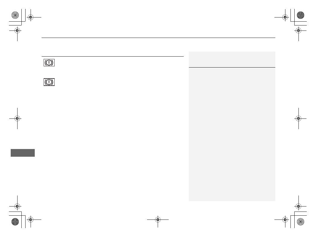
If the Brake System Indicator (Red) Comes On or Blinks at the Same Time When the Brake System Indicator (Amber) Comes On

Han

d

lin
g the U

n

expected

If the Brake System Indicator (Red) Comes On or Blinks at the 
Same Time When the Brake System Indicator (Amber) Comes On

If the Brake System Indicator (Red) comes on or blinks at the 
same time when the Brake System Indicator (Amber) comes on, 
release the parking brake manually or automatically

2

Parking Brake

 P. 500

If the Brake System Indicator (Red) continuously comes on or blinks at 
the same time when the Brake System Indicator (Amber) comes on, 
stop the vehicle in a safe place and have it inspected by a dealer 
immediately.

u

Preventing the vehicle from moving
Put the transmission into 

(

P

.

If only the Brake System Indicator (Red) is turned off, avoid using the 
parking brake and have your vehicle checked by a dealer immediately.

1

If the Brake System Indicator (Red) Comes On or Blinks at the 
Same Time When the Brake System Indicator (Amber) Comes On

If you apply the parking brake, you may not be able 
to release it.

If the brake system indicator (red) and the brake 
system indicator (amber) come on at the same time, 
the parking brake is working.

If the brake system indicator (red) blinks at the same 
time when the brake system indicator (amber) comes 
on, the parking brake may not work because it is 
checking the system.

(Red)

(Amber)

659

uu

Indicator, Coming On/Blinking

u

If the Low Tyre Pressure/Deflation Warning System Indicator Comes On or Blinks

Han

d

lin
g the U

n

expected

If the Low Tyre Pressure/Deflation Warning System 
Indicator Comes On or Blinks

Reasons for the indicator to come on or blink

A tyre pressure is significantly low, or the deflation warning system has 
not been calibrated. If there is a problem with the deflation warning 
system, the indicator blinks for about one minute, and then stays on.

What to do when the indicator comes on

Drive carefully and avoid abrupt cornering and hard braking.
Stop your vehicle in a safe place. Check the tyre pressure and adjust the 
pressure to the specified level. The specified tyre pressure is on a label on 
the driver side doorjamb.

u

Calibrate the deflation warning system after the tyre pressure is 
adjusted.

2

Deflation Warning System Calibration

 P. 421

What to do when the indicator blinks, then remains on

Have the tyre inspected by a dealer as soon as possible.

1

If the Low Tyre Pressure/Deflation Warning System Indicator 
Comes On or Blinks

NOTICE

Driving on an extremely underinflated tyre can cause 
it to overheat. An overheated tyre can fail. Always 
inflate your tyres to the prescribed level.

660

uu

Indicator, Coming On/Blinking

u

If the Transmission System Indicator Blinks along with the Warning Message

Han

d

lin
g the U

n

expected

If the Transmission System Indicator Blinks along 
with the Warning Message

Reasons for the indicator to blink

The transmission is malfunctioning.

What to do when the indicator blinks

Immediately have your vehicle inspected by 
a dealer.

Put the transmission into 

(

N

 after turning 

the power system on.

u

Check if the 

(

N

 position in the 

instrument panel and the indicator on 
the 

(

N

 button light/blink.

u

The power system cannot be turned on 
unless the parking brake is set.

2

Turning on the Power

 P. 381

1

If the Transmission System Indicator Blinks along with the 
Warning Message

You may not be able to turn on the power system.

Make sure to set the parking brake when parking 
your vehicle.

Call a professional towing service if you need to tow 
your vehicle.

2

Emergency Towing

 P. 671

661

uu

Indicator, Coming On/Blinking

u

If the Power System Indicator Comes On

Han

d

lin
g the U

n

expected

If the Power System Indicator Comes On

Reasons for the indicator to come on

Comes on when there is a problem with the electric vehicle system or 
plug-in charging system.

Comes on when the High Voltage battery temperature becomes high.

What to do when the indicator comes on

Avoid high speeds and immediately get your vehicle inspected by a 
dealer.

662

Han

d

lin
g the U

n

expected

Fuses

Fuse Locations

If any electrical devices are not working, set 
the power mode to VEHICLE OFF (LOCK) 
and check to see if any applicable fuse is 
blown.

Fuse Box A

Located near the 12-volt battery. Push the 
tabs to open the box.
Locate the fuse in question by the following 
image and table.

Fuse Box inside the Bonnet

a

Tabs

a

Front

663

uu

Fuses

u

Fuse Locations

Continued

Han

d

lin
g the U

n

expected

Circuit protected and fuse rating

Circuit Protected

Amps

1

FUSE BOX SUB

40 A

ESB

40 A

ABS/VSA FSR

40 A

RELAY MODULE 1

30 A

IG MAIN 2

30 A

IG MAIN

30 A

MAIN FUSE

150 A

2

EPS

70 A

FUSE BOX MAIN 2

50 A

ABS/VSA MOTOR

40 A

COOLING FAN

60 A

FUSE BOX OPTION 2

50 A

RELAY MODULE 2

30 A

3

R/BOX MAIN 1

40 A

FRONT DEICER RIGHT

*

30 A

FUSE BOX OPTION 1

40 A

FUSE BOX MAIN 1

40 A

BLOWER MOTOR

40 A

4

POWER WINDOW MAIN 1

60 A

POWER WINDOW MAIN 2

60 A

REAR DEFROSTER

40 A

FRONT DEICER LEFT

*

30 A

5

COOLING FAN CONTROL

5 A

6

WIPER

30 A

Circuit Protected

Amps

7

STOP LIGHTS

10 A

8

IGA

10 A

9

IGB

10 A

10

BACK UP P/P

10 A

11

DT ELECTRIC WATER 

PUMP 2

10 A

12

13

HEAD LIGHT CONTROL LEFT

10 A

14

HEAD LIGHT CONTROL 

RIGHT

10 A

15

DT ELECTRIC WATER PUMP

15 A

16

BATTERY SENSOR

7.5 A

17

IGMG ECU

7.5 A

18

BACK UP

10 A

19

AUDIO

15 A

20

WASHER

15 A

21

ES VLV1

7.5 A

22

ES VLV2

7.5 A

23

HORN

10 A

24

ES ELECTRIC COOLANT 

HEATER

10 A

25

ES ELECTRIC WATER PUMP

10 A

26

FRONT FOG LIGHT

15 A

27

CHARGE LID ACTUATOR

10 A

* Not available on all models

664

uu

Fuses

u

Fuse Locations

Han

d

lin
g the U

n

expected

Fuse Box B

a

Tab

Pull up the cover on the 

+

 terminal, then 

remove it while pulling out the tab as 
shown.

Replacement of fuses inside the bonnet 
should be done by a dealer.

Circuit protected and fuse rating

Circuit Protected

Amps

BATTERY FUSE

175 A

665

uu

Fuses

u

Fuse Locations

Continued

Han

d

lin
g the U

n

expected

Fuse Box A

Located behind the instrument panel.

Locate the fuse in question by the following 
image and table.

Driver Side Interior Fuse Box

Left-hand drive type

Right-hand drive type

a

UP

666

uu

Fuses

u

Fuse Locations

Han

d

lin
g the U

n

expected

Circuit protected and fuse rating

Circuit Protected

Amps

1

2

LEFT SIDE DOOR UNLOCK

10 A

3

RIGHT SIDE DOOR UNLOCK

10 A

4

ACC

10 A

5

6

SRS

10 A

7

8

P-ACT ECU

7.5 A

9

KEYLESS ACCESS

10 A

10

REAR FOG

10 A

11

LEFT SIDE DOOR LOCK

10 A

12

13

RIGHT SIDE DOOR LOCK

10 A

14

OPTION

10 A

15

DAYTIME RUNNING LIGHT

5 A

16

17

WIDE MONITOR

10 A

18

HAZARD

10 A

19

CENTRE CAMERA MIRROR 

SYSTEM

7.5 A

20

QUICK CHARGEING 

SYSTEM

10 A

Circuit Protected

Amps

21

22

23

COMBO

10 A

24

IMG

10 A

25

SHIFTER

7.5 A

26

LEFT SIDE CAMERA MIRROR 

SYSTEM

10 A

27

RIGHT SIDE CAMERA 

MIRROR SYSTEM

10 A

28

ABS/VSA

7.5 A

29

ELECTRIC POWER PLANT

7.5 A

30

31

REAR USB CHARGER

10 A

32

OPTION

10 A

33

34

FRONT SEAT HEATERS

20 A

35

ACG

10 A

36

METER

10 A

37

OPTION

10 A

38

39

40

HEATED STEERING WHEEL

*

10 A

Circuit Protected

Amps

41

IGC

10 A

42

43

AUDIO SUB

7.5 A

44

PREMIUM AMP

*

20 A

45

REAR WIPER

10 A

46

SRS

10 A

47

48

A/C MAIN

10 A

49

DOOR LOCK

20 A

50

FRONT ACCESSORY 

SOCKET

20 A

51

52

A/C ELECTRIC WATER 

PUMP

10 A

53

SUPER LOCK

*

20 A

54

POPUP DOOR OUTER 

HANDLE

15 A

55

* Not available on all models

667

uu

Fuses

u

Fuse Locations

Continued

Han

d

lin
g the U

n

expected

Fuse Box B

Located under the fuse box A.

a

Fuse Box B

Left-hand Drive Type

a

Fuse Box B

Right-hand Drive Type

Locate the fuse in question by the following 
image and table.

Circuit protected and fuse rating

a

UP

Circuit Protected

Amps

1

LEFT REAR POWER 

WINDOW

30 A

2

PASSENGER'S POWER 

WINDOW

30 A

3

RIGHT REAR POWER 

WINDOW

30 A

4

DRIVER'S POWER WINDOW

30 A

668

uu

Fuses

u

Fuse Locations

Han

d

lin
g the U

n

expected

Located under the luggage area floor lid.

Remove the floor lid from the luggage area.
Push the tabs to open the box.

Rear Fuse Box

a

Floor Lid

a

Tabs

Locate the fuse in question by the following 
image and table.

Circuit protected and fuse rating

a

Front

Circuit Protected

Amps

1

EOP

20 A

2

P-ACT

30 A

3

4

5

669

uu

Fuses

u

Inspecting and Changing Fuses

Continued

Han

d

lin
g the U

n

expected

Inspecting and Changing Fuses

1.

Set the power mode to VEHICLE OFF 
(LOCK). Turn headlights and all accessories 
off.

2.

Check the fuses on the battery inside the 
bonnet.

u

If the fuse is blown, have it replaced by a 
dealer.

3.

Remove the fuse box cover.

4.

Inspect the small fuses inside the bonnet 
and the vehicle interior.

u

If there is a blown fuse, remove it with 
the fuse puller and replace it with a new 
one.

1

Inspecting and Changing Fuses

NOTICE

Replacing a fuse with one that has a higher rating 
greatly increases the chances of damaging the 
electrical system. 

Replace a fuse of the same specified amperage.
Use the charts to locate the fuse in question and 
confirm the specified amperage.

2

Fuse Locations

 P. 662

There is a fuse puller in the fuse box A inside the 
bonnet.

a

Blown

Fuse Box on the Battery

a

Fuse Puller

670

uu

Fuses

u

Inspecting and Changing Fuses

Han

d

lin
g the U

n

expected

5.

Check the large fuse inside the bonnet.

u

If the fuse is blown, use a phillips-head 
screwdriver to remove the screw and 
replace it with a new one.

Combined Fuse

a

Blown Fuse

671

Han

d

lin
g the U

n

expected

Emergency Towing

Call a professional towing service if you need to tow your vehicle.

Flat bed equipment

The operator loads your vehicle on the back of a truck.
This is the only way you can safely transport your vehicle.
Any other towing method will damage the vehicle’s drive system.

1

Emergency Towing

NOTICE

Trying to lift or tow your vehicle by the bumpers will 
cause serious damage. The bumpers are not designed 
to support the vehicle's weight.

Improper towing such as towing behind a 
motorhome or other motor vehicle can damage the 
transmission.

Never tow your vehicle with just a rope or chain.
It is very dangerous since ropes or chains may shift 
from side to side or break.

672

Han

d

lin
g the U

n

expected

If You Cannot Open the Charge Lid

If you cannot open the charge lid, use the following procedure.

1.

Open the bonnet.

2

Opening the Bonnet

 P. 592

2.

Pull the release lever near the charge lid.

What to Do If Unable to Open the Charge Lid

1

If You Cannot Open the Charge Lid

After taking this step, contact a dealer to have the 
vehicle checked.

a

Bonnet Release Handle

a

Release Lever

673

Han

d

lin
g the U

n

expected

If You Cannot Disengage the Charging Connector

When 

 Appears on the Driver Information Interface

 appears on the driver information interface when you cannot disengage the 

charging connector.
Disengage the charging connector as follows.

1.

Make sure that charging is completed 
correctly.

2.

Pull down the release cord which is located 
under the glove box.

u

The release cord returns to its original 
position at the next charging.

3.

The charging connector to disengage it 
from the inlet.

If the Remote Battery Is Weak

The charging connector cannot be disengaged if the door is locked while the keyless 
remote cannot be detected, such as when the battery is weak.
You can disengage the charging connector by pressing the release button in the 
inlet by unlocking the door with the built-in key.

2

Replacing the Button Battery

 P. 620

2

If the Keyless Remote Battery is Weak

 P. 649

What to Do If Unable to Disengage the Charging Connector

1

If You Cannot Disengage the Charging Connector

If the problem that you cannot disengage the 
charging connector occurs repeatedly, contact a 
dealer to have the vehicle checked.

a

Release Cord


Content      ..     40      41      42