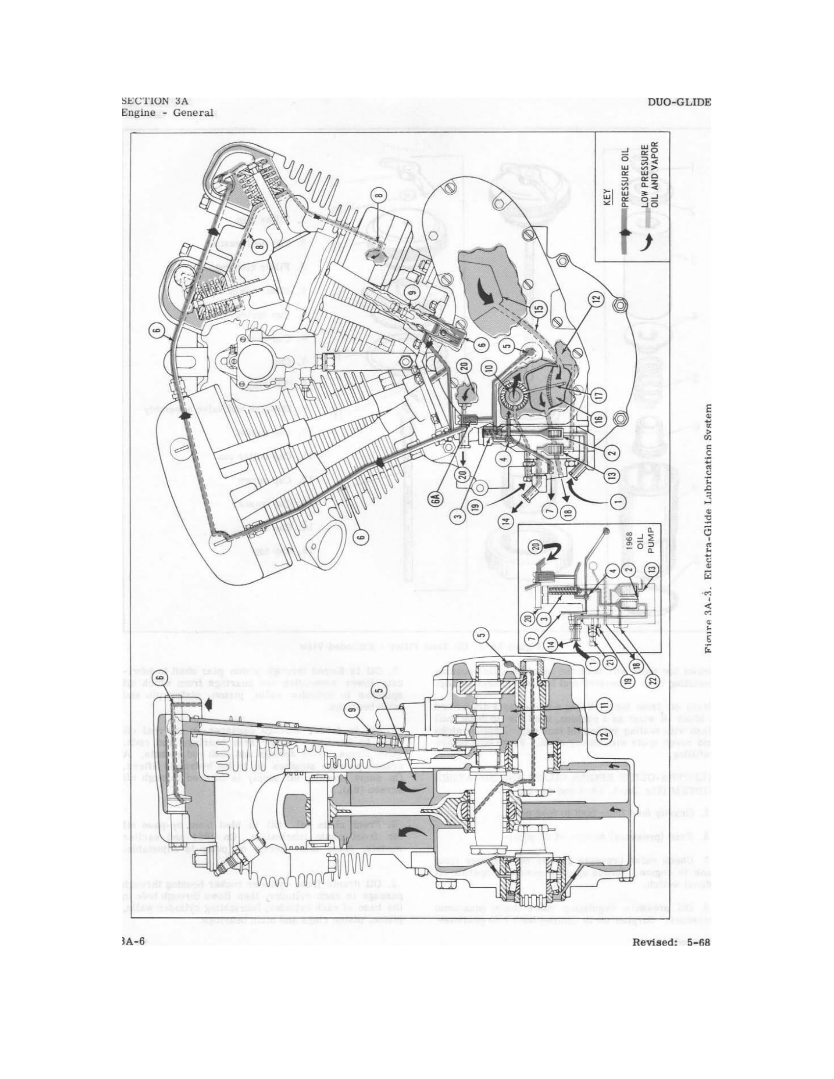
Harley Davidson Electra Glide. Service manual (1959 to 1969) - page 5
ELECTRA-GLIDE ENGINE OILING AND BREATHER SYSTEM
(Fig. 3A-3, 3A-4 and 4A-4A)
1. Gravity feed from tank to feed pump.
2. Feed (pressure) section of oil pump.
3. Check valve prevents gravity oil drainage from tank to engine. Builds
up oil pressure to operate oil signal switch.
4. Oil pressure regulating valve limits maximum pressure. Surplus oil is
dumped bar’-, into gearcase.
5. Oil is forced through pinion gear shaft to
lubricate lower connecting rod bearings from which oil splashes to
cylinder walls, piston, piston pin and main bearings.
6. Oil is forced through passages or external oil lines to lubricate
rocker arm bearings and rods, valve stems, valve springs and push rod
sockets. A branch passage supplies oil to the hydraulic lifters. On some
models, oil supply is filtered through oil screen (6A).
7. Front chain oil. Oil is bled from by-pass oil for front chain
lubrication. On 1964 and earlier models, chain oiler screw on pump is
adjustable.
8. Oil drains from cylinder rocker housing through passage in each
cylinder, then flows through hole in the base of each cylinder,
lubricating cylinder walls, piston, piston rings and main bearings.