Harley Davidson Electra Glide FL/FLH, Super Glide FX/FXE/FXEF/FXS (1978 1/2 to 1980). Service manual - page 4
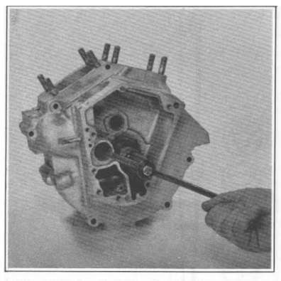
Figure 3-43. Lapping Pinion Shaft Main Bearing Race
Assemble lapping arbor to lapping handle and assemble guide sleeve to
sprocket shaft bearing bushing. Sleeves for use with tapered bearing,
are assembled to case with bearings and small spacer collar. Turn sleeve
parts finger tight.
Insert lap shaft with arbor assembled through pinion bearing bushing and
into guide sleeve. Tighten arbor expansion collars using a length of
5/32 in. rod as spanner until arbor begins to drag. Do not adjust arbor
snug in bushing or bushing will “bell/' a condition where hole is larger
at ends than it is in the center.
Withdraw arbor far enough to coat lightly with fine lapping compound. Do
not apply a heavy coat. Reposition lap in bushing and turn handle at
moderate hand speed. Work lap back and forth in bushing as it is
revolved to avoid grooving and tapering.
At frequent intervals, remove lap from crankcase, wash and inspect
bushing. Lapping is completed when entire bushing surface has a dull,
satin finish rather than a glossy, smooth appearance. If necessary,
flush off lap in cleaning solvent, air dry and apply fresh, light coat
of fine lapping compound.
FITTING PINION SHAFT BEARING
The fitting of pinion shaft bearing is done in much the same way as
fitting lower rod bearings (see "Fitting Rod Bearings"). A plug fit is
first determined using the pinion shaft that will be used on engine
being overhauled, or spare shaft of exactly same size. When a plug fit
has been found, pinion shaft will enter bearing slowly under its own
weight, will turn with only a very light drag and will have no
perceptible shake.
A running fit is determined from a plug fit by subtracting
one half the desired running fit clearance from the size ol the plug fit
rollers.
Example:
Running fit clearance is 0.0005 to 0.001 in. loose. See "Engine
Specifications," Section 3. If a plug fit wa« achieved with 0.0006 in.
oversize rollers, subtract one half running fit clearance from plug fit
roller oversize. Use figure representing middle or average of tolerance
span, 0.00075 or 0.0008 in. One half the average of tolerance (0.0004
in.), subtracted from roller oversize (0.0006 in.), indicates that
0.0002 in. oversize rollers should be usee to produce a suitable running
fit.
Oversize rollers are available in 0.0002, 0.0004, 0.0006, 0.0008 and
0.001 in. sizes. All calculations should therefore be made to nearest
available even-numbered size. In the ex ample above, it would be
possible to arbitrarily decide upon 0.0006 in. as a running fit rather
than the 0.0008 in. il desired. Final decision would rest largely upon
intended use of motorcycle. For highspeed work, the more free fit would
be better, while the closer tolerance is suited to road use at average
speeds. This consideration may be made in fitting all tolerances.
All fitting must be done with bearings that are clean and dry. Oiled
surfaces will take up some clearance and give a false reading.
FITTING SPROCKET BEARING
If flywheel end play is within tolerance and if Timken tapered roller
bearings and races pass visual check and have no apparent wear, the same
set may be reinstalled. Make certain all parts of bearing are installed
in exactly the same order they were removed. If any part of bearing
assembly is worn, entire assembly should be replaced.
ASSEMBLING CRANKCASE (Figure 3-31)
Install flywheel side outer race snap ring (12) in case. When properly
installed, oil hole in snap ring groove will be centered in snap ring
gap. Use arbor press and Outer Race Press Plug, Part No. 97194-57 to
press outer race parts into crankcase bushing one at a time. Press the
races into the case, one from each side, with the widest ends outward to
match taper of bearings. Be sure each race bottoms on the snap ring.
Position flywheel assembly, sprocket shaft up, in vise with copper jaws.
Press bearing (15) on sprocket shaft using Bearing Installing Tool, Part
No. 97225-55. Sprocket shaft spacer 24036-66 may be needed with bearing
installing tool as shown in figure 3-44. Press the parts on using
sprocket shaft spacer as a pressing tool only. Turn tool screw onto
sprocket shaft thread and tighten securely. Remove tool and slip the
bearing, small end up, over sprocket shaft, starting it squarely.
Install the small bearing spacer (10) and tool sleeve and press bearing
against flange on flywheel