Great Wall Hover. Service Manual - part 16


  Index      Great Wall     Great Wall Hover. Service Manual


Search            copyright infringement  


Content      ..     14      15      16      17     ..


Great Wall Hover. Service Manual - part 16


circlip

circlip pliers

special tools

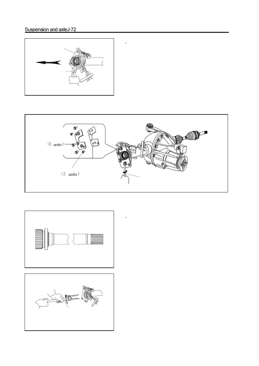
8. Use the special tools to remove the major semiaxle

oil seal.

Caution: Do not scratch the inner surface of flange.

6

Use the circlip pliers to remove the circlip

which clamp the major semiaxle bearing outer race.

7

Use the special tools to remove the major

semiaxle and bearing, circlip assembly.

liftout bolt 

bolt pin

Pad

special tools

-------------------------------------------------------------------------------------------------------------------------------------------------------------

9. Remove the sealant on the matching surface

between the flange and electric clutch housing by

knife.

Caution: Do not scratch the matching surface.

10. Use the special tools to knock the new seal in the

oil seal position in flange.

Caution: Before install the new oil seal, it should

coat the lip with thin lithium base grease, and the oil

seal should be in alignment position.

11. Insert the spline of small end of major semiaxle

in the spline of front reducer half axle gear slightly,

then use the brass bar and hand hammer to knock it

in.

Caution: When knock in the major semiaxle, must

not damage the inside needle bearing of large end

spline of major semiaxle.

12. Use the circlip pliers to install the circlip in the

flange and clamp the bearing outer race.

Caution: The circlip should be replaced if it has

serious deformation.

13. Use the clean cloth to wipe the matching surface

of flange and electric clutch housing respectively.

-------------------------------------------------------------------------------------------------------------------------------------------------------------

14. Align the spline of mechanical wheel of separator

with the spline in front drive shaft and separator

shift fork sleeve, and install it in the front drive

shaft and separator shift fork sleeve.

15. Coat the flange matching surface with the 1596

silicon rubber plane sealant uniformly and level it by

plate.

Caution: Ensure the continuity of sealant and avoid

the sealant enter into the screw hole.

16. Align the shift fork bush with the spline on the

major semiaxle to make the mechanical wheel of

separator enters into the major semiaxle, then use

the bolt to connect the electric clutch housing and

front axle pipe flange and tighten it to the specified

torque. In which the bolt should be precoated with

the screw locking agent (drip one or two drops on the

middle of screw).

specified torque : 90-110N

m

Caution: Prevent the foreign material from entering into the

front drive axle during assembly.

17. Use the wrench to tighten the bolt of vent tube

bracket to tightening torque.

Tightening force: 23-26N

m

18. Screw off the oil filling plug on the electric clutch

housing, remove the washer and fill it with the gear

lubrication oil until flush with the bottom of oil

filling port.

Number of lubrication oil: GL-5

19. Place the washer of oil filling plug, tighten the oil

filling plug to specified torque.

Specified torque: 140-150N.m

-------------------------------------------------------------------------------------------------------------------------------------------------------------

20. Connect the vent tube on the electric clutch

housing to the front axle vent tube connector

assembly.

21. Connect the electric clutch vent tube to the

front axle vent tube connector assembly.

connect the place

connect the place

-------------------------------------------------------------------------------------------------------------------------------------------------------------

Disassembly and assembly of front reducer assembly and electric clutch

adjusting shim

bearing gland

differential housing

driven bevel gear

front drive axle housing

washer

oil filling plug

vent tube

clip

front axle vents tube
connector assembly

major semiaxle

needle bearing

electric clutch

location pin

vent tube

mechanical wheel of separator

declutch shift sleeve

electric clutch housing

oil filling plug

circlip

major semiaxle oil seal

half axle gear thrust plate

half axle gear

planetary gear shaft

planetary gear

bolt  

clump

weight bracket

clump weight and bush
assembly

clump weight bracket
welded assembly

front reducer
housing

adjusting washer

spacer 

drive bevel gear

small bearing

oil seal

front drive gear flange and

dustproof cover assembly

drive bevel gear

adjusting washer

Pregummed component

 N 

m:  Specified torque

Used component which

can not be used any more.

bearing

circlip

big bearing

-------------------------------------------------------------------------------------------------------------------------------------------------------------

Disassembly of front reducer assembly

1. Remove the front drive axle and left and right

front drive shaft assembly.

(Refer to “Removal of Front Reducer Assembly”

and “Removal of Front Drive Shaft Assembly”)

2. Disconnect three interface positions of front drive

axle vent tube connector assembly.

3. Use the flat screwdriver to pry off the clip fixed

the vent tube connector assembly and take out

the vent tube connector assembly.

4. Screw off the bolt fixed the electric clutch and use

the brass bar to knock down the electric clutch.

5. Use the wrench to remove the oil filling plug;

remove the washer and pull out the vent tube.

6. Use the wrench to remove the bolt connected to

the electric clutch housing and front axle tubeflange;

take out the shift fork sleeve and mechanical wheel

of separator.

Caution: The leaked gear oil during disassembly

should be stored in the container to avoid the

pollution for environment.

disconnected in

this place

disconnected in this place

disconnected in this place

-------------------------------------------------------------------------------------------------------------------------------------------------------------

7. Use the circlip pliers to remove the circlip fixed

the major semiaxle bearing outer race.

8. Use the special tools to pull out the major semiaxle

and major semiaxle bearing with the major semiaxle

inner race circlip.

 (Refer to “Replacement of Major Semiaxle Oil Seal”)

9. Use the special tools to remove the major semiaxle

oil seal.

 (Refer to “Replacement of Major Semiaxle Oil Seal”)

10. Pull out the vent tube on the front axle tube.

11. Use the circlip pliers to remove the circlip. Fasten

the major semiaxle bearing inner race.

12. Press out the major semiaxle bearing on press

machine. (Or knocked out by hand hammer)

Caution: Don’t damage the end spline of major

semiaxle.

13. Use the special tools to pull out the needle bear-

ing in major semiaxle.

Caution: It should use the pad when use the vise to

clamp the major semiaxle.

14. Use the wrench to remove the bolt which is used

to fix the clump weight and axle bush assembly, take

off the clump weight and axle bush assembly.

special tools

-------------------------------------------------------------------------------------------------------------------------------------------------------------

15. Use the wrench to remove the bolt fixed the

clump weight bracket welded assembly.

16. Use the wrench to remove the bolt and nut used

to fix the front reducer assembly and front axle

housing.

17. Use the brass rod or hand hammer to knock the

front reducer housing to separate it from the front

drive axle housing.

18. Check the run-out of driven bevel gear.

Rotate the flange; use the dial indicator to measure

the run-out of driven bel gear.

Max. Runout: 0.07mm

It should replace the drive and driven bevel gear totally if the run-

out is more than 0.07mm.

19

Check the running clearance of drive and

driven bevel gear.

a. Install the dial indicator and ensure the side axis is vertical to

    contact tooth surface.

b. Hold the drive gear flange and rotate the driven bevel gear in

    clockwise and anticlockwise to measure the clearance.

Specified range of clearance: 0.15-0.25mm

Remarks: Check three average points on circumference of driven

bevel gear at least.

-------------------------------------------------------------------------------------------------------------------------------------------------------------

20. Check the engaging mark of drive and driven

bevel gear.

(Refer to “Assembly of Front Reducer Assembly”)

21. Measure the pre-applied load of drive bevel gear

bearing.

Use the torque measuring meter to measure the preapplied

load on the gap between the drive and drivenbevel gear.

Range of pre-applied load: 1.2-1.7N.m

22. Measure the total pre-applied load of drive bevel

gear.

23 Remove the drive gear flange and dustproof cover

assembly.

a. Use the hand hammer and chisel to loose the riveted part of

      drive gear nut.

b. Use the special tools to clamp the drive gear flange and

remove the drive gear nut.

c.   Use the brass rod to knock down the drive gear flange and

 dustproof cover assembly.

-------------------------------------------------------------------------------------------------------------------------------------------------------------

25. Use the special tools to remove the small

bearing inner race, and then reverse the reducer

to slide out the spacer.

Remarks: The bearing should be replaced by new

one if damaged.

26. Use the wrench to remove two bearing glands.

Remarks: It should distinguish the left and right of

the bearing gland when remove it to avoid the

confusion.

Remove the side bearing outer race and marked

with L and R.

29. Remove the left and right adjusting washer; mea-

sure its thickness; marked with left and right.

27. Use the brass rod to vibrate the differential

assembly upwardly, then take out the differential

assembly.

holding

pliers

special tools

rotate the wrench in clockwise

24. Use the special tools to remove the drive gear oil

seal.

-------------------------------------------------------------------------------------------------------------------------------------------------------------

30. Remove the drive bevel gear, then take out the

adjusting washer under spacer.

Check and replacement of reducer

1. Replace the big bearing of drive bevel gear .

a. Use the special tools to press out the big bearing of drive

       bevel gear.

Caution: It should replace the drive and driven bevel gear in

pair before replace the big bearing if the drive bevel gear is

damaged.

special

special

special

b. Install the washer on the drive bevel gear, Use the special

tools to install the new big bearing .

2. Replace the big bearing outer race of drive bevel

gear.

a. Use the brass bar and hand hammer to knock down the big

bearing outer race.

b. Use the special tools to press in the new big bearingouter race.

Special tools

-------------------------------------------------------------------------------------------------------------------------------------------------------------

3. Replace the small bearing of drive bevel gear.

a. Use the brass rod and hand hammer to knock down the small

      bearing outer race of drive bevel gear.

b. Use the special tools to press in the new bearing outer race.

c. Replace it by the new bearing inner race when installs the

small bearing..

4

Remove two side bearing inner races from the

differential housing.

a

Use the special tools to remove the side bearing inner race on

the side of differential  assembly with bolt.

b. It should pay attention to does not damage the driven bevel

gear when use the vice for clamping to remove the bearing

inner race on another side.

5.  Use the wrench to remove the bolt fastened the

driven bevel gear

Caution: It should make the assembly mark on the

driven bevel gear and differential housing before

disassembly.

6

Disassembly of differential assembly

a.   Use the hand hammer and special tools to knock out the pin

after remove the driven bevel gear.

special tools

rubber pad

assembly mark

rubber pad

special tools

-------------------------------------------------------------------------------------------------------------------------------------------------------------

b. Knock out the planetary gear shaft, rotate the half axle gear to

take out the planetary gear, then take out the half axle gear

and thrust plate.

7. Assembly of differential assembly.

a. Wash the differential housing.

b. Cover the half axle gear thrust plate with the half axle gear,

    then installs it in the differential housing.

c. Rotate the half axle gear; install the planetary gear in rolling

    and insert the planetary gear shaft.

d.  Use the special tools to hit the pin to fix the planetary gear

shaft, and rivet the inserted hole to prevent the loose of pin.

Remarks: The rotation of half axle gear and planetary gear

should be smooth and without block; push the planetary gear

to inside, then use the dial indicator to measure the clearance

between the half axle gear thrust plate and differential

housing.

Rational clearance range: 0.4-0.75mm

It is necessary to replace the half axle gear thrust plate if the

clearance is beyond the previous range, at the same time ensure the

thrust plate in left and right side has the same thickness.

e.  Check the clearance between the half axle gear thrust plate and

differential housing.

special tools

-------------------------------------------------------------------------------------------------------------------------------------------------------------

f. Clean the surface of differential housing; use the brass rod to

install the driven bevel gear on the differential housing.

Caution:  It should align the marked assembly mark when

install the driven bevel gear and knock it in uniformly in

circumference ; it should remove the cooper chip in time if it

is adhered on  the driven bevel gear.

    g.   Coat the fastening bolt of driven bevel gear with the screw

          lock agent, then tighten it to the specified torque.

 Specified tightening force: 80-95N

m

Caution: It should be in the diagonal sequence to tighten the

bolt and tighten it for little, then tighten it to the specified

torque uniformly.

h.   On press machine, use the special tools to press the inner

race of bearing into the bearing position on both sides of

differential housing.

i.

Place an adjusting shim in the position of front reducer

housing side bearing near exterior.

     j.

Install another adjusting shim and the other side bearing outer

race in the front reducer housing with thedifferentialassembly

k.   Install two bearing glands, left and right and use the wrench

to tighten the bolt to the specified torque.

 Specified torque : 90-115N.m

special tools

special tools

bearing

bearing

adjusting shim

adjusting

shim

-------------------------------------------------------------------------------------------------------------------------------------------------------------

1.Rotate the driven bevel gear, check the runout of

driven bevel gear.

Max. Runout: 0.07mm

Assembly of front reducer assembly

1.Install the adjusting washer in the drive bevel gear,

install the big bearing inner race of drive bevel gear

by press.

2. Clean the front reducer housing, install the outer

race of big and small bearing on the reducer housing

by press..

3. Install the drive bevel gear into the front reducer

housing, then install the washer, spacer and small

bearing inner race.

4.Use the special tools to install the drive bevel gear

oil seal.

Caution: It should coat the lip with the oil seal

lithium base grease before install it and the rear

surface of rear oil seal should flush with the top of

front reducer housing after knocked in.

5. Install the drive gear flange and dustproof cover

assembly.

(Refer to “Replacement of Drive Bevel Gear Oil Seal”)

6.Use the special tools to tighten the drive gear nut

to the specified torque; the nut should be precoated

with the lithium base grease.

specified torque : 140-200N

m

7. Use the torque measuring meter to measure the

pre-applied load of big and small bearing of drive

bevel gear.

Range of pre-applied load: 1.2-1.7N

m

special tools

-------------------------------------------------------------------------------------------------------------------------------------------------------------

8. Place the differential assembly on the corresponding

position of front reducer housing.

9.Select an adjusting shim and insert it in a side of

side bearing outer race; push the differential assem-

bly to the side with adjusting shim.

10. Use the dial indicator to measure the gear side

clearance of driven bevel gear and drive bevel gear;

select out the adjusting shim in the side which meets

the rational clearance of 0.15mm.

11.Measure the thickness of the adjusting shim.

12. After select out one side adjusting shim, then

select theadjusting of another side according to that

the theoreticthickness of the adjusting shimofanother

side equals to subtracting the thickness of selected

shim and oppositiondistance L2 between outer race of

two side bearings of differential assembly from the

opposition distance L1 between two side bearings of

front reducer housing.

-------------------------------------------------------------------------------------------------------------------------------------------------------------


Content      ..     14      15      16      17     ..