Geely Emgrand X7. Manual part - 251


  Главная      Geely     Geely Emgrand X7 - Manual


поиск по сайту            


содержание   ..  249  250  251  252  ..


Geely Emgrand X7. Manual part - 251
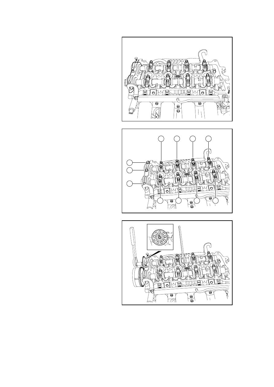


4.  Install the intake and exhaust 

camshaft cover. 

There are letters on the camshaft 
cover. Avoid installation errors. For 
example, "I ↑ 2" indicates that the 
camshaft cover is the No.2 intake 
camshaft cover. The arrow is toward 
the direction of timing chain. E ↑ 2 
indicates the No.2 exhaust camshaft 
cover. The arrow is toward the 
direction of timing chain. 

FE02-0183b

5.  Tighten camshaft cover bolts in 

the order as showed in the figure.

Note: Tighten the bolts during 
several stages. Do not tighten at once 
which may damage the camshaft and 
the camshaft cover. 

Torque :M6 bolt   

13N.m(Metric)10lb-ft(English 
system) 

M8 Bolt   

23 N.m(Metric)17lb-ft(English 
system) 

3

1

6

8

9

7

11

5

2

4

10

FE02-0184b

6.  Install the exhaust camshaft 

sprocket. 

Note: Inspect the sprocket pin wear. 
If there is wear, replace the sprocket 
pin. Hold the camshaft with a wrench 
and then tighten the VVT actuator 
bolts. 

Torque :55N .  m(Metric) 
41lb-ft(English system) 

FE02-0185b

1003

7.  Install the intake camshaft VVT 

actuator. 

Note: Inspect the VVT actuator pin 
wear. Hold the camshaft with a 
wrench and then tighten the sprocket 
bolts. 

Torque :70N .  m(Metric) 
52lb-ft(English system) 

8.  Install timing chain 

9.  Install the timing chain cover. 

10.  Install the drive belt. 

11.  Install the cylinder hood cover. 

12. Install the plastic shield of 

engine. 

13.  Connect battery negative cable. 

FE02-0186b

1004

2.13.8.13 Replacement of Engine 

Dismantlement Procedure 

1.  Dismantle battery negative cable,refer to 2.11.8.1 Disconnect connecting process of battery 

cable 

2.  Release the fuel pressure. Refer to 2.3.8.1 Fuel Pressure Release Procedure. 

3.  Discharge engine coolant. Refer to 2.8.8.1 Engine Coolant Discharge and Filling. 

4.  Refer to 2.8.8.2 "Replacement of 

Coolant Recovery Reservoir" to 
dismantle the coolant recovery 
reservoir. 

5. Recover the air-conditioning 

refrigerant. Refer to 8.2.7.12 
Air-conditioning Refrigerant 
Recovery and Filling. 

6.  Remove battery base plate, Refer 

to 2.11.8.2 Battery Replacement.

7.  Refer to 12.8.3.3 "Replacement 

of Glove Box of the Instrument 
Panel" to dismantle the glove 
box of the instrument panel. 

8.  Disconnect the engine control 

unit and engine harness to the 
instrument panel harness 
connectors. 

NL02-0171b


9.  Pull the engine harness out of 

the firewall. 

NL02-0172b


1005

10. Disconnect front and rear 

oxygen sensor wiring harness 
connectors. 

NL02-0173b


11. Dismantle the air-conditioning 

compressor high and low 
pressure connecting tubes. 

NL02-0174b


12. 

Dismantle intake air pipe 
assembly. 

NL02-0175b


1006


содержание   ..  249  250  251  252  ..