Geely Emgrand X7. Manual part - 250


  Главная      Geely     Geely Emgrand X7 - Manual


поиск по сайту            


содержание   ..  249  250  251  ..


Geely Emgrand X7. Manual part - 250
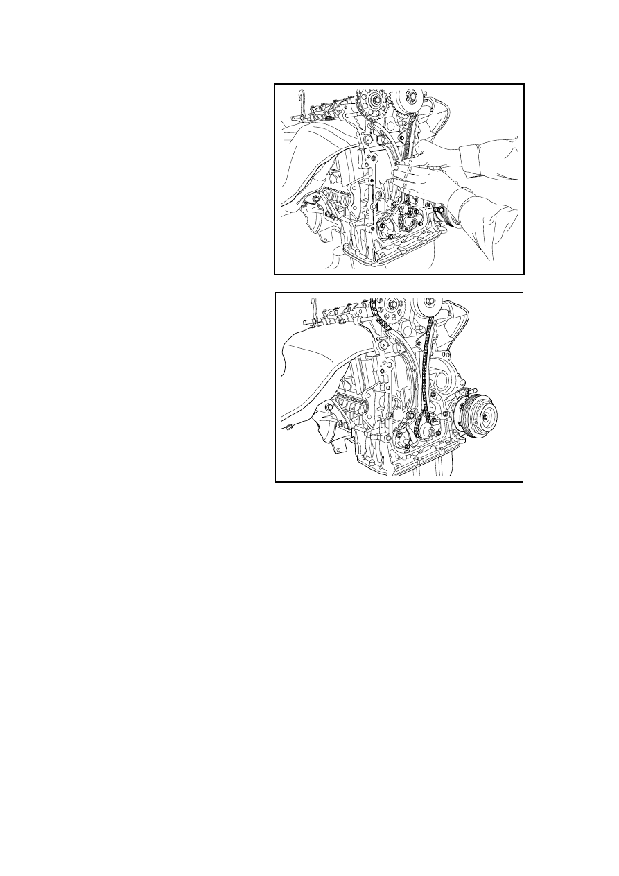


8.  Install the fixing bolt for the 

tensioning guide rail assembly. 

Tightening torque: 19N.m (Metric) 
14lb-ft (Inch) 

FE02-0173b

9.  Install the crankshaft chain wheel 

retainer ring. 

10.  Install the timing chain cover and 

accessories. 

FE02-0158b

999

2.13.8.11 Timing Chain Inspection 

1.  Refer to 2.13.8.9 “Replacement 

of Timing Chain Shroud” to 
dismantle the timing chain 
shroud. 

2.  Refer to 2.13.8.10 "Replacement 

of Timing Chain" to dismantle 
the timing chain. 

3.  Inspect timing chain guide rail 

component for cracking, wear 
and tear. 

4.  If abrasion depth of chain 

guideway component surface 
exceeds 1mm (0.04in), replace 
timing chain guideway 
component. 

5.  Inspect timing chain tensioner 

rail component for wear and tear.

6.  If the the surface of the chain 

tensioning guide rail component 
is worn to a depth more than 
1mm (0.04in), then replace the 
timing chain tensioning guide rail 
component. 

FE02-0175b

7.  Check whether the timing chain and VVT actuator chain wheel are worn. 

8.  Check the exhaust cam shaft sprocket and VVT actuator sprocket and chain for excessive 

wear, breakage or any signs of dead jamming with the timing chain connecting rod. 

9.  Inspect the crankshaft timing sprocket teeth and chain for excessive wear, broken, or stuck. 

10.  Inspect whether timing chain tensioner is damaged, sealing pad is in good condition, if it is 

damaged, replace timing chain tensioner and sealing pad. 

11.  Inspect timing chain lubrication 

nozzles. If necessary, dismantle 
the oil pump assembly.  Inspect 
the oil channel. Refer to 2.9.8.1 
“Replacement of Oil Pump”. 

FE02-0176b

1000

2.13.8.12 Replacement of Camshaft 

Dismantlement Procedure 

1.  Disconnect the battery negative electrode cable. Refer to 2.11.8.1 Battery Disconnection. 

2.  Dismantle the plastic shield of 

engine. Refer to 2.13.8.1 
Replacement of Plastic Shield of 
Engine. 

3.  Refer to 2.13.8.2 "Replacement 

of Cylinder Hood Cover" to 
dismantle the cylinder hood 
cover. 

4.  Dismantle the drive belt. Refer to 

2.13.8.3 Replacement of Drive 
Belt. 

5.  Refer to 2.13.8.9 "Replacement 

of Timing Chain Cover" to 
dismantle the timing chain cover.

FE02-0177b

6.  Refer to 2.13.8.10 "Replacement 

of Timing Chain" to dismantle 
the timing chain. 

7.  Dismantle the intake camshaft 

VVT actuator. 

Note: Dismantle the camshaft VVT 
actuator tightening bolt with a 
wrench holding the camshaft. 

8.  Dismantle the exhaust camshaft 

sprocket. 

Note: Dismantle the camshaft 
sprocket tightening bolts with a 
wrench holding the camshaft.
 

FE02-0178b

9.  Gradually loosen the camshaft 

bearing cap bolts in the order as 
shown in the figure and loosen 
by one half or one circle each 
time. 

Special Precautions: Be careful when 
dismantling the camshaft. Avoid 
abrasions, scratches or damage to the 
camshaft surface or bearing surface.
 

9

11

6

4

3

5

1

7

10

8

2

FE02-0179b

1001

10. Dismantle the camshaft. 

Important precaution : Camshaft 
must be withdraw from the bearing in 
order to avoid abrasions, scratches or 
damage to the camshaft surface or 
bearing surface
. 


11. Inspect for the camshaft and 

bearing wear.  If 

necessary, 

replace. 

FE02-0180b

Installation Procedure: 

Precaution: be careful to install the 
camshaft. Avoid abrasions, scratches 
or damage to the camshaft surface or 
bearing surface. 

Special Precautions: Before 
installation,apply engine lubrication 
oil to the camshaft journal and the 
seal contacting surface. 

1.  Apply a small amount of engine 

oil to lubricate the journal and 
camshaft cap. 

2.  Install the exhaust camshaft. 

FE02-0181b

3.  Install the intake camshaft. 

FE02-0182b

1002


содержание   ..  249  250  251  ..