содержание .. 444 445 446 447 448 449 450 ..
Geely EC718, EC718RV, EC715, EC715RV. Manual part - 449
3
1
4
2
5 6
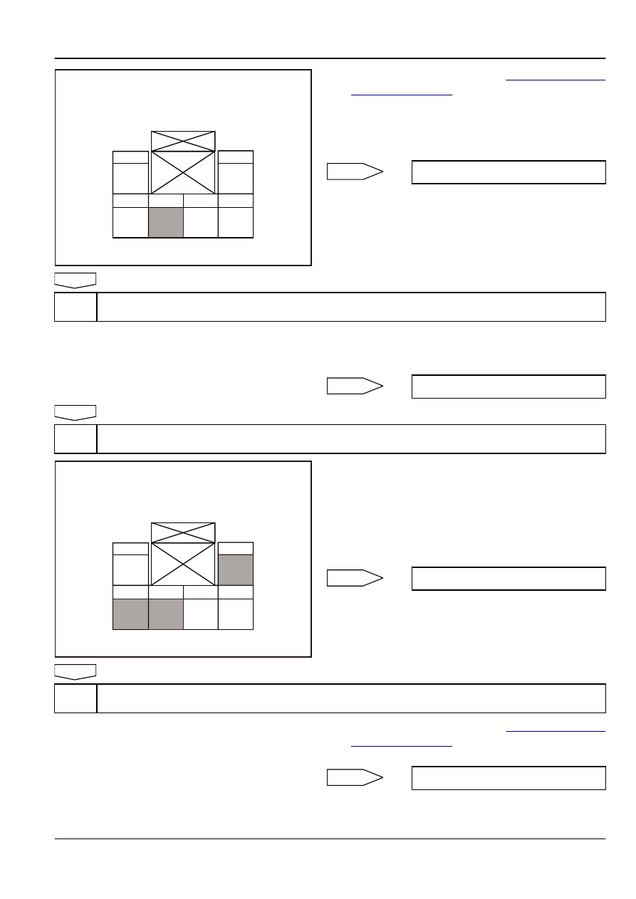
Interior Light + Sunroof Switch Harness
Connector RF06
FE11-5703b
(a)
Remove the sunroof switch. Refer to
.
(b)
Measure resistance between the sunroof switch harness
connector RF06 and body ground with a multimeter.
Standard Resistance: Less than 1 Ω
Is the resistance specified value?
Yes
No
Step 5
Repair the open circuit between the sunroof switch harness connector RF06 and body ground.
(a)
Confirm the open circuit between the sunroof switch harness
connector RF06 and body ground repair is completed.
Is the sunroof working properly?
Yes
System normal
No
Step 6
Check the sunroof switch assembly.
3
1
4
2
5 6
Interior Light + Sunroof Switch Harness
Connector RF06
FE11-5704b
(a)
Press the sunroof switch, while measure resistance between
the switch RF06 terminals 2,3 and 4 with a multimeter.
(b)
Measure resistance between sunroof switch harness
connector RF06 terminals 4 and body ground with a
multimeter.
Standard Resistance: Less than 1 Ω
Is the resistance specified value?
Yes
No
Step 7
Replace the sunroof switch.
(a)
Install a new sunroof switch. Refer to
.
Is the sunroof working properly?
Yes
System normal
Body Electric
Sunroof
11-309