Geely EC718, EC718RV, EC715, EC715RV. Manual part - 313


  Главная      Geely     Geely Emgrand EC718, EC718RV, EC715, EC715RV. Workshop Manual year 2009


поиск по сайту            


содержание   ..   310  311  312  313  314  ..


Geely EC718, EC718RV, EC715, EC715RV. Manual part - 313


No

Properly connect the connector.

Yes

Step 3

Check the wiring harness (instrument cluster - power, ground).
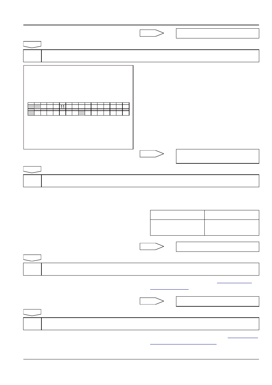
15 14 13 12 

10 9 8 7  6 5 4 3 2 1 

16 

32 31 30 29 28 27 26 25 24 23 22 21 20 19 18  17 

Instrument Cluster Harness Connector IP03

FE09-5105b

(a)

Turn the ignition switch to OFF.

(b)

Disconnect the battery negative cable.

(c)

Disconnect the instrument cluster harness connector IP03.

(d)

Connect the battery negative cable.

(e)

Turn the ignition switch to ON (IG).

(f)

Measure voltage between the connector IP03 terminals
24,32 and the body ground respectively with a multimeter.
Standard Voltage Value: 11-14 V

(g)

Turn the ignition switch to OFF.

(h)

Measure resistance between the connector IP03 terminals
15,16 and the body ground respectively with a multimeter.
Standard Resistance: Less than 1 Ω

Is the resistance specified value?

No

Check the fuses, repair or replace the wiring
harness.

Yes

Step 4

Check the instrument cluster.

(a)

Connect scan tool, turn the ignition switch to ON (IG).

(b)

In the functional test, select "Active test."
Active Test: ABS Warning Lamp

Display

Test Parts

ABS Warning Lamp

ABS Warning Lamp lit or not
lit (ON / OFF)

(c)

Check whether the ABS Warning Lamp is working properly.

Yes

System normal

No

Step 5

Replace the instrument cluster.

(a)

Replace instrument cluster. Refer to 

11.7.7.1


Instrument

Cluster Replacement

.

(b)

Check whether the ABS Warning Lamp is working properly.

Yes

System normal

No

Step 6

Replace the hydraulic electronic control unit.

(a)

Replace the ABS control module. Refer to 

6.6.7.1


Hydraulic

Electronic Control Unit Replacement

.

(b)

Check whether the ABS Warning Lamp is working properly.

Brake System

ABS / TCS / EBD / ESP

6-85

(c)

Confirm that the repair is completed.

Next

Step 7

System normal.

6.6.6.10 Power Failure and Hydraulic Electronic Control Unit Assembly Internal Fault Diagnosis

DTC code

Description

C1101

ECU Power Supply Voltage: High Voltage

C1102

ECU Power Supply Voltage: Low Voltage

C2112

Valve Relay Fault

C2308

Valve Malfunction, Left Front Inlet Valve

C2312

Valve Malfunction, Left Front Outlet Valve

C2316

Valve Malfunction, Right Front Inlet Valve

C2320

Valve Malfunction, Right Front Outlet Valve

C2324

Valve Malfunction, Left Rear Inlet Valve

C2328

Valve Malfunction, Left Rear Outlet Valve

C2332

Valve Malfunction, Right Backward Valve

C2336

Valve Malfunction, Right Rear Inlet Valve

C2402

Return Pump Malfunction (Electrical and Electronic Failure)

6-86

ABS / TCS / EBD / ESP

Brake System

Schematic:

CA13

CA13

CA13

CAN H

CAN L

IF13

EF21

EF20

CA13

CA13

CA13

32

26

13

38

CA13

CA13

14

17

IP12

7

1

25

SO30

2

SO30

1

SO28

2

SO28

1

CA26

2

CA26

1

CA07

2

CA07

1

CA13

19

CA13

31

CA13

33

CA13

20

CA13

18

CA13

6

CA13

34

CA13

22

Datalink 
Connector

ABS Control Module

Right Rear 
Wheel Speed 
Sensor

Left Rear 
Wheel Speed 
Sensor

Right Front 
Wheel Speed 
Sensor

Left Front 
Wheel Speed 
Sensor

FE06-5604b

Diagnostic Steps:

Step 1

Check the battery.

(a)

Measure the battery voltage.
Standard Voltage Value: 11-14 V

Is the voltage specified value?

No

Check and replace the battery or the charging
system.

Yes

Step 2

Check the ABS control module harness connector.

(a)

Check whether the wiring harness connector is connected
correctly.

No

Properly connect harness connectors.

Yes

Step 3

Check the ABS control module harness connector (terminal voltage).

Brake System

ABS / TCS / EBD / ESP

6-87

1

25

38

13

37

36

35

34

33

32

31

30

29

28

27

14 15 16 17 18 19 20 21 22 23 24

12

11

10

9

8

7

6

5

4

3

2

26

ABS Control Module Harness Connector 

FE06-5605b

(a)

Turn off the ignition switch.

(b)

Disconnect the control module harness connector.

(c)

Turn on the ignition switch.

(d)

Measure voltage between the harness connector CA13
terminals 1,25 32 and the body ground with a multimeter.
Standard Voltage Value: 11-14 V

Is the voltage specified value?

No

Check the fuses, repair or replace the wiring
harness

Yes

Step 4

Check the ABS control module harness connector (ground terminal continuity).

1

25

38

13

37

36

35

34

33

32

31

30

29

28

27

14 15 16 17 18 19 20 21 22 23 24

12

11

10

9

8

7

6

5

4

3

2

26

ABS Control Module Harness Connector CA13

FE06-5606b

(a)

Measure resistance between the harness connector CA13
terminals 13, 38 and the body ground with a multimeter.
Standard Resistance: Less than 1 Ω

Is the resistance specified value?

No

Repair or Replace the wiring harness or the
connector.

Yes

Step 5

Replace the hydraulic electronic control unit

(a)

Replace the ABS control module assembly. Refer to

6.6.7.1


Hydraulic Electronic Control Unit Replacement

.

(b)

Connect the battery negative cable.

(c)

Turn the ignition switch, to confirm whether the ABS Warning
Lamp lit out.

(d)

Confirm that the repair is completed.

Next

Step 6

System normal.

6.6.6.11 Wheel Speed Sensor Fault Diagnosis

DTC code

Description

C1200

Wheel Speed Sensor, Left Front: Open / Short

6-88

ABS / TCS / EBD / ESP

Brake System


содержание   ..   310  311  312  313  314  ..