Geely EC718, EC718RV, EC715, EC715RV. Manual part - 312


  Главная      Geely     Geely Emgrand EC718, EC718RV, EC715, EC715RV. Workshop Manual year 2009


поиск по сайту          


содержание   ..   310  311  312  313  ..


Geely EC718, EC718RV, EC715, EC715RV. Manual part - 312


Terminal ID

Name

Wiring

Terminal

Descriptions

Status

Specified

Conditions

31

WSRR

0.5 Y/G

Right Rear Wheel

Speed Sensor


32

IG2

0.85 G/Y

ON Power Supply


33

WPRL

0.5 W/L

Left Rear Wheel

Speed Sensor


34

WPFL

0.5 W

Left Front Wheel

Speed Sensor


35

Empty

Empty

Empty


36

Empty

Empty

Empty


37

Empty

Empty

Empty


38

GND

2.5 B

Empty


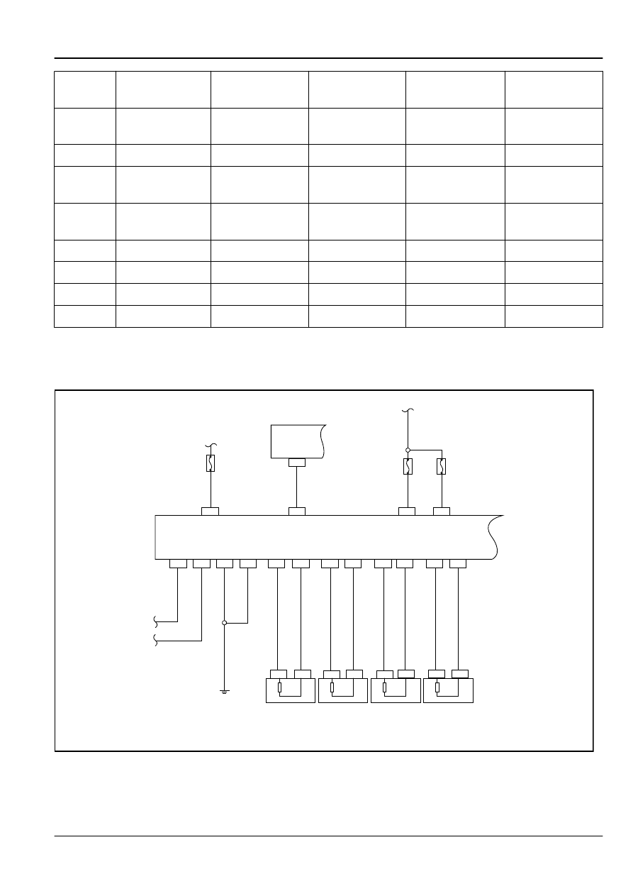
6.6.6.8 ABS Warning Lamp Always On

Schematic:

CA13

CA13

CA13

CAN H

CAN L

IF13

EF21

EF20

CA13

CA13

CA13

32

26

13

38

CA13

CA13

14

17

IP12

7

1

25

SO30

2

SO30

1

SO28

2

SO28

1

CA26

2

CA26

1

CA07

2

CA07

1

CA13

19

CA13

31

CA13

33

CA13

20

CA13

18

CA13

6

CA13

34

CA13

22

Datalink 
Connector

ABS Control Module

Right Rear 
Wheel Speed 
Sensor

Left Rear 
Wheel Speed 
Sensor

Right Front 
Wheel Speed 
Sensor

Left Front 
Wheel Speed 
Sensor

FE06-5604b

Brake System

ABS / TCS / EBD / ESP

6-81

Diagnostic Steps:

Step 1

Use scan tool to access ABS control module.

(a)

Check the DTC.

Yes

Repair according to the DTC.

No

Step 2

Check the battery.

(a)

Measure battery voltage with a multimeter.
Standard Voltage Value: 11-14 V

Is the voltage specified value?

No

Charge the battery, or check the charging
system.

Yes

Step 3

Check the ABS control module harness connector.

(a)

Check whether the wiring harness connector is connected
correctly.

No

Properly connect the harness connectors.

Yes

Step 4

Check the ABS control module harness connector (terminal voltage).

1

25

38

13

37

36

35

34

33

32

31

30

29

28

27

14 15 16 17 18 19 20 21 22 23 24

12

11

10

9

8

7

6

5

4

3

2

26

ABS Control Module Harness Connector 

FE06-5605b

(a)

Turn off the ignition switch.

(b)

Disconnect the control module harness connector.

(c)

Turn on the ignition switch.

(d)

Measure voltage between the CA13 terminals 1,25,32 and
the body ground with a multimeter.
Standard Voltage Value: 11-14 V

Is the voltage specified value?

No

Check the fuses, repair or replace the wiring
harness

Yes

Step 5

Check the ABS control module harness connector (ground terminal Continuity).

6-82

ABS / TCS / EBD / ESP

Brake System

1

25

38

13

37

36

35

34

33

32

31

30

29

28

27

14 15 16 17 18 19 20 21 22 23 24

12

11

10

9

8

7

6

5

4

3

2

26

ABS Control Module Harness Connector CA13

FE06-5606b

(a)

Measure resistance between the connector CA13 terminals
13.38 and the body ground with a multimeter.
Standard Resistance: Less than 1 Ω

Is the resistance specified value?

No

Repair or Replace the wiring harness or the
connectors.

Yes

Step 6

Replace the hydraulic electronic control unit assembly.

(a)

Replace the hydraulic electronic control unit. Refer to

6.6.7.1


Hydraulic Electronic Control Unit Replacement

.

(b)

Connect the battery positive cable.

(c)

Turn on the ignition switch to confirm whether the ABS
Warning Lamp is lit.

Yes

System normal

No

Step 7

Check the instrument cluster.

(a)

Connect scan tool.

(b)

In the functional test, select "Active test."
Active Test: ABS

Display

Test Parts

ABS Warning Lamp

ABS Warning Lamp Lit or
Not Lit (ON / OFF)

(c)

Check whether the ABS Warning Lamp is working properly.

Yes

System normal

No

Step 8

Replace the instrument cluster control unit.

(a)

Disconnect the battery negative cable. Refer to

2.11.8.1


Battery Disconnection

.

(b)

Replace the instrument cluster control unit. Refer to

11.7.7.1


Instrument Cluster Replacement

.

(c)

Confirm that the repair is completed.

Brake System

ABS / TCS / EBD / ESP

6-83

Next

Step 9

System normal.

6.6.6.9 ABS Warning Lamp Always Off

Schematic:

CA13

CA13

CA13

CAN H

CAN L

IF13

EF21

EF20

CA13

CA13

CA13

32

26

13

38

CA13

CA13

14

17

IP12

7

1

25

SO30

2

SO30

1

SO28

2

SO28

1

CA26

2

CA26

1

CA07

2

CA07

1

CA13

19

CA13

31

CA13

33

CA13

20

CA13

18

CA13

6

CA13

34

CA13

22

Datalink 
Connector

ABS Control Module

Right Rear 
Wheel Speed 
Sensor

Left Rear 
Wheel Speed 
Sensor

Right Front 
Wheel Speed 
Sensor

Left Front 
Wheel Speed 
Sensor

FE06-5604b

Diagnostic Steps:

Step 1

Check the battery.

(a)

Measure the battery voltage.
Standard Voltage Value: 11-14 V

Is the voltage specified value?

No

Check and replace the battery or the charging
system.

yes

Step 2

Check the instrument cluster connector.

(a)

Turn the ignition switch to OFF.

(b)

Disconnect the negative battery cable.

(c)

Check whether the connectors are properly connected to the
instrument cluster.

6-84

ABS / TCS / EBD / ESP

Brake System


содержание   ..   310  311  312  313  ..