Geely EC718, EC718RV, EC715, EC715RV. Manual part - 303


  Главная      Geely     Geely Emgrand EC718, EC718RV, EC715, EC715RV. Workshop Manual year 2009


поиск по сайту            


содержание   ..   300  301  302  303  304  ..


Geely EC718, EC718RV, EC715, EC715RV. Manual part - 303


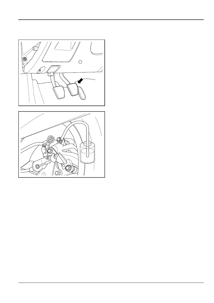
container with brake fluid inside. Discharge the right rear
brake caliper air according to the following steps.

FE06-0051b

8.

Slowly press the brake pedal, do not press the brake pedal
abruptly.

FE06-0050b

9.

Press the brake pedal, at the same time, loosen the air
discharge screw, exhaust the air in the brake caliper.

10. When bubbles emerge in the brake fluid container, slightly

tighten the air discharge screw.

11. Slowly release the brake pedal.

12. Wait  for  20  s,  repeat  steps  6-9  until  all  the  air  is

discharged.

13. Loosen the air discharge screw, if the bubble no longer

appears  in  the  container,  this  indicates  that  the  air  has
been fully discharged.

Note

In  the  exhaust  process,  leave  the  master  cylinder
tank fluid level at least more than half.

14. Tighten the air discharge screw.

Torque: 6.5 Nm (Metric) 4.8 lb-ft (US English)

Brake System

Hydraulic Brake

6-45

FE06-0051b

15. Discharge air in sequence of the left front, left rear and

right front brake caliper. Follow the steps 5-12.

16. After discharging all the brake caliper air, check whether

the  brake  pedal  is  soft  and  whether  the  pedal  has  no
resistance at all. repeat the entire discharge process, until
the pedal is normal.

6.4.5.6 Vacuum Booster Replacement

Removal Procedure:

Warning!

Refer to "Battery Disconnect Warning" in "Warnings and
Notices".

2

1
2

2

2

FE06-0052b

1.

Disconnect  the  battery  negative  cable.  Refer  to

2.11.8.1


Battery Disconnection

.

2.

Remove the brake fluid tank and the brake master cylinder
assembly.  Refer  to 

6.4.5.2


Brake  Master  Cylinder

Replacement

.

3.

Remove the vacuum hose.

4.

Remove the Instrument panel lower left panel. Refer to

12.8.3.1


Instrument Panel Replacement

.

5.

Separate the vacuum booster rod U-shape clip and the
brake pedal.

6.

Remove the clutch / brake pedal assembly retaining nuts
(2).

6-46

Hydraulic Brake

Brake System

FE06-0053b

7.

Remove the vacuum booster.

1

2

3

FE06-0054b

8.

Release  the  connecting  rod  U-shape  clip  locking  nut,
remove the U-shape clip and the locking nut (1).

9.

Remove the spring clip (2).

10. Remove the rubber sleeve and gasket (3).

Note

If the rubber sleeve is damaged or aging, replace it
and the gasket.

Installation Procedure:

1

2

3

FE06-0055b

1.

Install  a  new  gasket,  install  the  rubber  sleeve  to  the
booster rod.

2.

Install the spring clip (2).

3.

Install the U-shape clip and the U-shape rod locking nut,
and tighten the nut 3.

Brake System

Hydraulic Brake

6-47

137mm

FE06-0056b

4.

Adjust the U-shape rod clip travel.

U-shape rod clip and the booster rear end distance:137
mm (5.39 in).

5.

Tighten the U-shape clip lock nut.

Torque: 20 Nm (Metric) 14.8 lb-ft (US English)

FE06-0057b

6.

Install the vacuum booster.

1

2
1

1

1

FE06-0058b

7.

Tighten the clutch / brake pedal assembly retaining nuts
(1).

Torque: 23 Nm (Metric) 17.0 lb-ft (US English)

8.

Connect  the  vacuum  booster  U-shape  rod  clip  and  the
brake pedal (2).

9.

Install the Instrument panel lower left panel.

10. Install the vacuum hose.

11. Install the brake fluid tank and the brake master cylinder

assembly.

6.4.5.7 Brake Fluid Level Sensor Replacement

Removal Procedure:

Warning!

Refer to "Battery Disconnect Warning" in "Warnings and
Notices".

6-48

Hydraulic Brake

Brake System


содержание   ..   300  301  302  303  304  ..