содержание .. 200 201 202 203 204 ..
Geely EC718, EC718RV, EC715, EC715RV. Manual part - 203
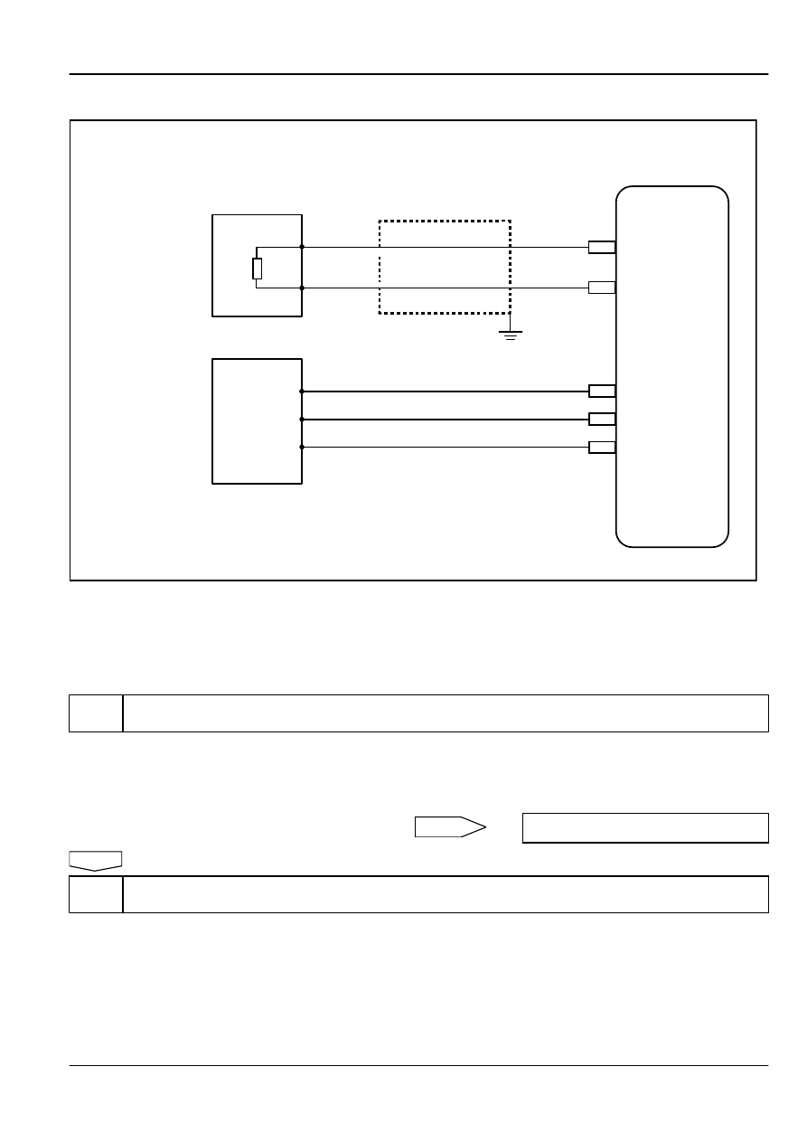
3. Schematic:
CPS HI
CPS LO
21
20
EO01
EO01
A
B
B
A
C
EO01
EO01
EO01
18
56
23
V5RTN2
CAM1
V5REF2
Crankshaft Position Sensor
Camshaft Position Sensor
Engine
Control
Module
FE02-5297b
4. Diagnostic Steps:
Note
Before carrying out this diagnosis step, observe the data list on scan tool and analyze the accuracy of the data, as
these will help with quick diagnosis.
Step 1
Initial Inspection
(a)
Check the sensor wiring harness connector EN26 whether
there is loose or poor connection and so on.
(b)
Check whether the sensor is installed correctly.
(c)
Check whether the sensor gap is normal.
No
Repair the faulty part. Go to step 10
Yes
Step 2
Read the engine data (engine speed) on the scan tool.
(a)
Connect scan tool to datalink connector.
(b)
Turn the ignition switch to "ON" position.
(c)
Select "Engine"/"Reading Data"/"Engine Speed."
(d)
Start the engine.
(e)
With the engine running, read the engine data on the scan
tool
Engine
Control System JL4G15-D
2-727