Geely EC718, EC718RV, EC715, EC715RV. Manual part - 120


  Главная      Geely     Geely Emgrand EC718, EC718RV, EC715, EC715RV. Workshop Manual year 2009


поиск по сайту            


содержание   ..  119  120  121  ..


Geely EC718, EC718RV, EC715, EC715RV. Manual part - 120


FE02-0213b

7.

Inspect  and  confirm  that  the  sealing  surface  has  no
distortion  and  warping  and  the  cylinder  head  sealing
surface flatness must be 0.05 mm (0.002 in).

8.

Inspect and confirm that valve seat ring has no excessive
wear and burnt places.

Installation Procedure:
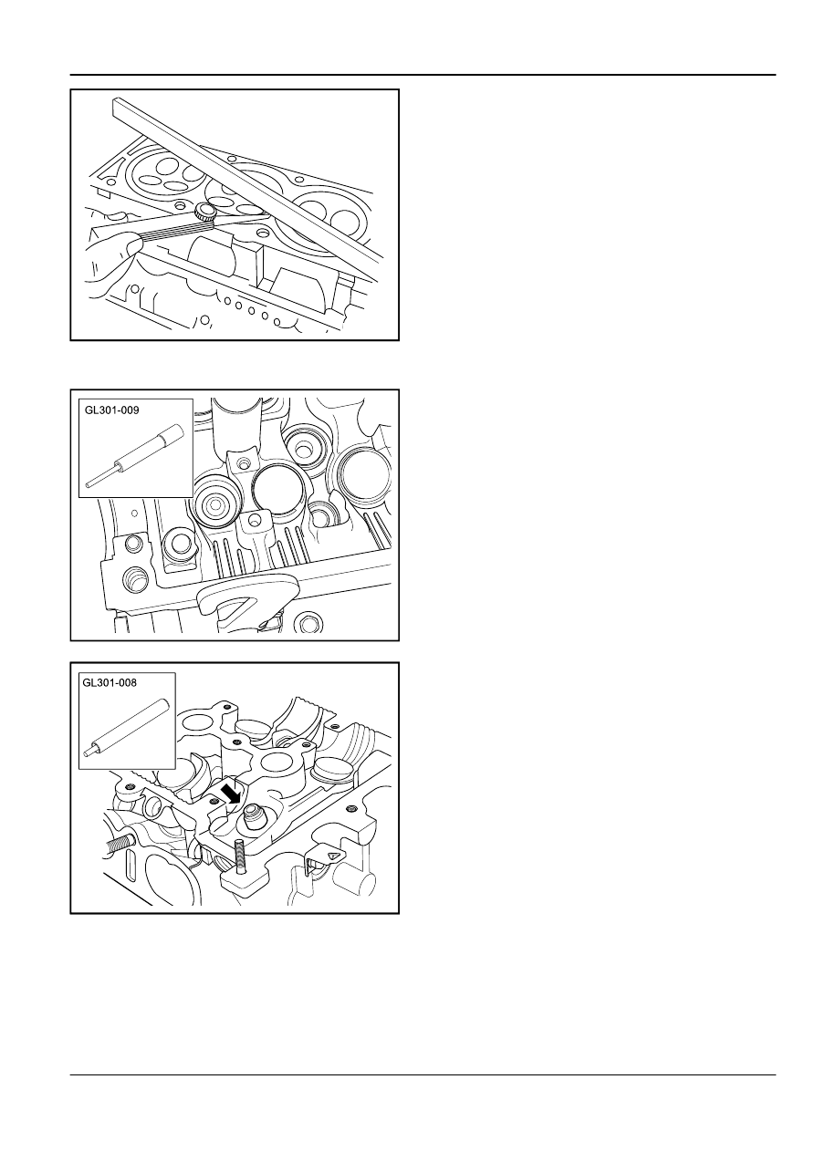
FE02-0502b

1.

Use a special tool GL301-009 to install the valve guide
rod.

FE02-0214b

2.

Use a special tool GL301-008 to install the special valve
seals.

Engine

Engine Mechanical System JL4G18-D

2-395

FE02-0215b

3.

Install the valves.

FE02-0216b

4.

Install the valve spring pads.

FE02-0217b

5.

Install the valve springs.

2-396

Engine Mechanical System JL4G18-D

Engine

FE02-0218b

6.

Install the valve spring seat.

FE02-0219b

7.

Use a universal tool to compress the valve springs and
install the valve spring locking pieces.

FE02-0220b

8.

Confirm  locking  pieces  is  in  place.  slowly  remove  the
special tool with a wood hammer gently knock the valve,
so that the valve is in place.

Warning!

Do not apply excessive force, otherwise the valve
spring might pop up and cause personal injury.

9.

Install the valve lifter.

10. Install the cylinder head assembly.

Engine

Engine Mechanical System JL4G18-D

2-397

2.6.8.16  Piston  Connecting  Rod  and  Bearing
Replacement

Removal Procedure:

FE02-0221b

1.

Remove the engine assembly. Refer to 

2.6.8.13


Engine

Replacement

.

2.

Remove  the  cylinder  head  cover.  Refer  to

2.6.8.14


Cylinder Head Assembly Replacement

.

3.

Remove  the  oil  pan.  Refer  to 

2.9.8.3


Oil  Pan

Replacement

.

4.

Remove the filters.

FE02-0222b

5.

Rotate the crankshaft, so that the cylinder NO.1 and 4 are
at BDC positions. Remove the cylinder NO.1 rod bearing
cap bolts.

FE02-0223b

6.

hold the rod bolts. Remove the cylinder NO.1 connecting
rod bearing caps and mark the location of the cylinder NO.
1 on the bearing cover.

2-398

Engine Mechanical System JL4G18-D

Engine


содержание   ..  119  120  121  ..