Freightliner Cascadia. Manual - part 27


  Index      Freightliner     Freightliner Cascadia - service manual


Search            


Content   ..  25  26  27  28   ..


Freightliner Cascadia. Manual - part 27


16. Install the jam nut on the driver-side inner tie rod,

and the tie rod clamp on the passenger-side
inner tie rod.

17. Thread the inner tie rods into the outer tie rods.

18. Attach the outer tie rods of the rack and pinion

gear to the tie rod steering arms. Tighten the
castellated nuts 240 lbf·ft (325 N·m). Continue to
tighten until the next castellated nut slot aligns
with the hole in the ball stud and insert the new
cotter pin.

19. Tighten the jam nut on the driver side, and the

tie rod clamp nut on the passenger side.

20. Align the steering gear.

NOTE: Use a calibrated, computerized,
multi-wheel alignment tool, operated by a
certified service technician to complete the
following steps. If this type of tool is not ac-
cessible, the alignment procedure must be
done by a facility that has the appropriate
tool.

When the alignment process requires that
the steering wheel be pointed straight
ahead, align the steering rack on-center
pointers instead. See

Fig. 11

.

20.1

Loosen the driver-side tie rod jam nut. If
necessary, hold the inner tie rod in place
with a backup wrench on the inner tie rod
flat. See

Fig. 4

.

20.2

Align the steering rack on-center pointers.

20.3

Place a wrench on the driver-side inner
tie rod flat and align the left tire by rotat-
ing the inner tie rod.

20.4

Tighten the tie rod jam nut 285 to 305
lbf·ft (386 to 414 N·m).
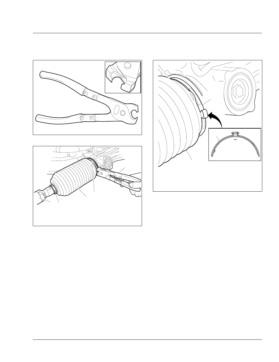
07/24/2009

f580473

Fig. 8, Oetiker Clamp Tool, P/N 14100037 or 14100082

07/21/2009

f462165

1

2

3

4

5

1.

Outer Tie Rod

2.

Small Oetiker Clamp

3.

Bellows

4.

Large Oetiker Clamp

5.

Oetiker Clamp Tool

Fig. 9, Oetiker Clamp Installation

08/25/2009

f462172

1

2

A

2

A. Crimp the clamp ears until the ear width is 0.08 to

0.16 inch (2 to 4 mm).

1.

Bellows

2.

Large Oetiker Clamp

Fig. 10, Oetiker Clamp Ear Width

Steering

46

46/7

20.5

Loosen the passenger-side tie rod clamp
nut.

20.6

With the gear on center, place a wrench
on the passenger-side inner tie rod flat
and align the right tire by rotating the
inner tie rod.

20.7

Tighten the tie rod clamp nut 30 to 36
lbf·ft (41 to 49 N·m).

IMPORTANT: Total toe-in should be between
0 and 1/8 inch (3.2 mm), and the target is
1/16 inch (1.6 mm).

20.8

Check the clearance of the front wheels.
With the tires on turnplates, and the
wheels turned all the way to the right and
left, there must be at least 1/2-inch (13
mm) clearance between the wheels and
stationary components, and at least 3/4-
inch (19 mm) clearance between the
wheels/tires and moving components. If
this is not the case, back out the stop
bolts and adjust the jam nuts to limit the
turning angles and to prevent possible
contact with components.

20.9

Tighten the stop-bolt jam nuts 80 to 120
lbf·ft (108 to 163 N·m).

NOTICE

Maximum wheel cut is not to exceed 46 degrees.
Excessive wheel cut may damage the inner tie
rod.

20.10 Verify that wheel cut does not exceed 46

degrees. Adjust wheel cut if needed.

21. Install both wheels on the steer axle.

22. Remove the jack stands and lower the vehicle.

05/31/2007

f462071

A

1

2

A. Align the pointers.
1.

Input Shaft Seal Cover

2.

Input Shaft Housing

Fig. 11, Rack and Pinion Pointer Alignment

Steering

46

46/8

MOP Number

CNG Fuel Cylinder Inspecting. . . . . . . . . . . . . . . . . . . . . . . . . . . . . . . . . . . . . . . . . . . . . . . . . . . . . . . . . 47–08

CNG Fuel System Inspecting . . . . . . . . . . . . . . . . . . . . . . . . . . . . . . . . . . . . . . . . . . . . . . . . . . . . . . . . . 47–06

CNG High-Pressure Fuel Filter Element Replacing . . . . . . . . . . . . . . . . . . . . . . . . . . . . . . . . . . . . . . . . . 47–07

Fuel Filter Replacement . . . . . . . . . . . . . . . . . . . . . . . . . . . . . . . . . . . . . . . . . . . . . . . . . . . . . . . . . . . . . 47–01

Fuel Tank Band-Nut Tightening. . . . . . . . . . . . . . . . . . . . . . . . . . . . . . . . . . . . . . . . . . . . . . . . . . . . . . . . 47–03

Fuel/Water Separator Element Checking and Replacement . . . . . . . . . . . . . . . . . . . . . . . . . . . . . . . . . . . 47–02

LNG Fuel System Inspecting . . . . . . . . . . . . . . . . . . . . . . . . . . . . . . . . . . . . . . . . . . . . . . . . . . . . . . . . . 47–04

LNG Vacuum Integrity Testing. . . . . . . . . . . . . . . . . . . . . . . . . . . . . . . . . . . . . . . . . . . . . . . . . . . . . . . . . 47–05

Safety Precautions . . . . . . . . . . . . . . . . . . . . . . . . . . . . . . . . . . . . . . . . . . . . . . . . . . . . . . . . . . . . . . . . . 47–00

Fuel

47

Index, Alphabetical

47–00 Safety Precautions

Safety Precautions in this section apply to all
procedures within this group.

DANGER

When working on the vehicle, shut down the en-
gine, set the parking brake, and chock the tires.
Before working under the vehicle, always place
jack stands under the frame rails to ensure the
vehicle can not drop. Failure to follow these steps
could result in serious personal injury or death.

47–01 Fuel Filter Replacement

For engine-mounted fuel filter replacement, refer to
the engine manufacturer’s service manual for re-
moval and installation procedures.

47–02 Fuel/Water Separator

Element Checking and
Replacement

Alliance/Racor

The only maintenance necessary on an Alliance or
Racor fuel/water separator is to replace the filter
element.

WARNING

Fluid circulated through the fuel/water separator
to heat the fuel may be diesel fuel returned from
the engine, or engine coolant. Drain the fuel/water
separator only when the engine and fluids have
cooled. Draining it when the engine is hot could
cause severe personal injury due to scalding.

If returning fuel is released into the atmosphere,
its vapors can ignite in the presence of any igni-
tion source. Do not expose the fuel to, or work
with the fuel system near, open flame or intense
heat. To do so could cause fire, possibly resulting
in serious personal injury or property damage.

1.

Drain off some fuel by loosening the vent plug
and opening the drain valve.

2.

Disconnect the water sensor and heater connec-
tions if equipped.

3.

Remove the element and bowl together, by turn-
ing counterclockwise.

4.

Remove the bowl from the element and clean
the O-ring land.

5.

Apply a coating of clean fuel or motor oil to the
new O-ring and element seal.

6.

Spin the bowl onto the new element, then spin
them both onto the filter head, snugly, by hand
only.

IMPORTANT: Do not use tools to tighten the
bowl and element.

7.

Connect the water sensor and heater connectors
if equipped.

8.

If equipped with a primer pump, prime the
fuel/water separator as follows.

8.1

Loosen the vent plug. Then operate the
primer pump until the fuel purges at the
vent plug. See

Fig. 1

.

8.2

Close the vent plug.

9.

Start the engine and check for fuel leaks.

10. Shut down the engine and correct any fuel leaks.

Davco Fuel Pro® 382 and 482

WARNING

Fluid circulated through the fuel/water separator
to heat the fuel may be diesel fuel returned from
the engine, or engine coolant. Drain the fuel/water
separator only when the engine and fluids have
cooled. Draining it when the engine is hot could
cause severe personal injury due to scalding.

If returning fuel is released into the atmosphere,
its vapors can ignite in the presence of any igni-
tion source. Do not expose the fuel to, or work
with the fuel system near, open flame or intense
heat. To do so could cause fire, possibly resulting
in serious personal injury or property damage.

The filter element should be changed only when the
fuel level has reached the top of the filter element.
There is no significant restriction to fuel flow until the
element is completely clogged.

Fuel

47

47/1


Content   ..  25  26  27  28   ..