Freightliner Cascadia. Manual - part 25
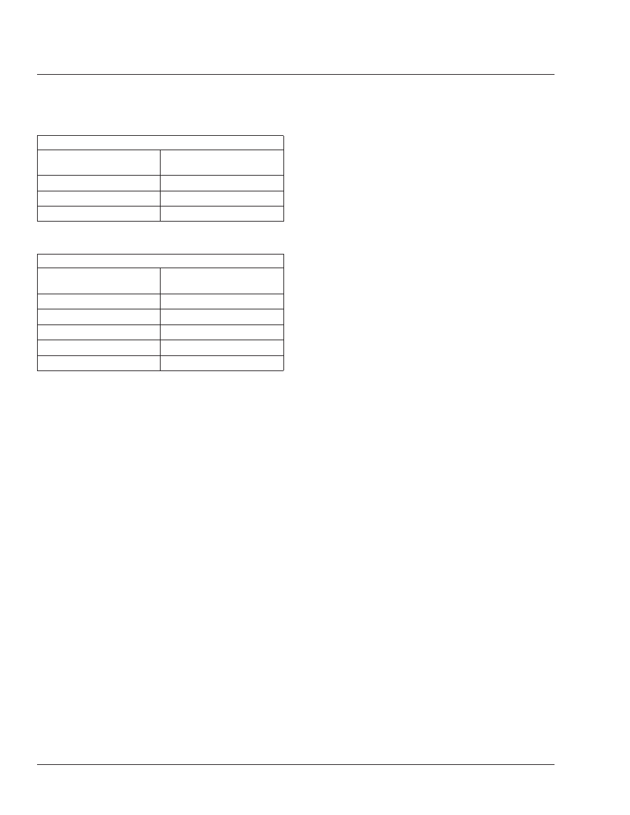
Actuator Stroke–Standard Stroke
Brake Actuator Size
Recommended Maximum
Operating Stroke (Inches)
20
1-3/4
16
1-3/4
12
1-3/8
Table 2, Actuator Stroke–Standard Stroke
Actuator Stroke–Long Stroke
Brake Actuator Size
Recommended Maximum
Operating Stroke (Inches)
30 Long Stroke
2-1/2
24 Long
2
24 Long Stroke
2-1/2
20 Long
2
16 Long
2
Table 3, Actuator Stroke–Long Stroke
Brakes
42
42/12