Foton Series Light Bus. Service Manual - part 8


  Index      Foton     Foton Series Light Bus. Service Manual


Search            copyright infringement  


Content      ..     6      7      8      9     ..


Foton Series Light Bus. Service Manual - part 8


OPERATION AND MAINTENANCE MANUAL FOR FOTON VIEW SERIES LIGHT BUS 


·104· 

via fuel return pipeline. 

4.2.10 Ignition Coil 

The  ignition  coil  assembly  integrates  the  ignition  module  and  two  ignition  coils  (shown  in  Figure  4-18). 

Primary  coil  is  controlled  by  ECM  through  ignition  module;  each  secondary  of  ignition  coil  is  connected  with 

spark plug in series inside two cylinders to form a loop. 


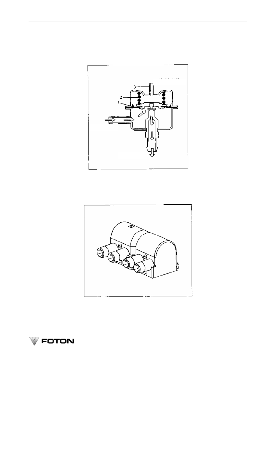
Figure 4-17 Working Principle of Fuel Pressure Regulator 

1-Pressure regulating diaphragm; 2-Pressure regulating spring; 3-Manifold pressure collection hole 


The primary coil resistance: 0.5 Ω±0.05Ω 


Figure 4-18 Ignition coil 


The secondary coil resistance: 5200Ω±400Ω 

Wiring: A-2, 3 cylinders ignition driving, B-1, 4 cylinders ignition driving, 

C-Grounding, D-+12V 

Pressure fuel 

Intake manifold   

Return fuel 

-------------------------------------------------------------------------------------------------------------------------------------------------------------

Chapter 4    BJ491EQ1 Gasoline Engine Fuel Injection System 


·105· 

4.2.11 High Voltage Cable and Spark Plug 

Because electronic fuel injection system adopts high energy and high voltage ignition, the high voltage cable 

must be endurable with high voltage, and also can restrain the radio interference occurred during ignition 

4.2.11.1 Check Spark Plug 

Use  the  steel  brush  to  clean  the  spark  plug.  Visual  check  plug  electrode  for  burnt-out,  damaged  thread  and 

insulator. Replace if plug is damanged. 

Type  of


spark plugs: F6RTC or  F5RTC; thread specification: M14×1.25. Bend the  side  electrode carefully 

and adjust the electrode clearance to its correct position: 1.1 mm ± 0. 1mm (see Figure 4-19). 


Figure 4-19    Check Spark Plug 


Installation torque of spark plug: 25 ~ 30 N.m. 

Replace the spark plug at every 10,000km normally. 

4.2.11.2 Check High Voltage Cable 

●  Caution: Do not pull or bend the high voltage cable, otherwise its inside conductor may be damaged (see 

Figure 4-20). 

High voltage cable is of damp type. Replace the high voltage cable if the resistance between its two ends is 

larger than 25 KΩ. 


Figure 4-20 Check High Voltage cable 


4.2.11.3 Check flashover in each cylinder 

Dismantle  at  the  same  time  the  spark  plugs  in  two  cylinders,  and  connect  them  with  corresponding  high 

Incorrect 

Correct 

-------------------------------------------------------------------------------------------------------------------------------------------------------------

OPERATION AND MAINTENANCE MANUAL FOR FOTON VIEW SERIES LIGHT BUS 


·106· 

voltage cable. Make sure plugs’ screw thread ground to cylinder block. Start up the gasoline engine to observe the 

flashover.   

●  Caution: To  observe the flashover, the injector in  concerning cylinder should be  unplugged. Otherwise 

unburned gasoline would burn near the three-way catalytic converter to damange injector immediately. Two spark 

plugs in a same group should be dismantled at the same time. Otherwise the ignition system may be damaged. 

4.2.12 Throttle Valve Body 

The  throttle  valve  body  is  installed  at  the  front  end  of  intake  manifold.  It  controls  air  intake  flow.  It  is 

composed by throttle body, valve, accelerating mechanism, throttle position sensor and idle speed air control valve 

(See Figure 4-21). 

4.2.12.1 Throttle Position Sensor 

The throttle position sensor monitors the throttle opening angle, and sends the signal to the ECM. The signal 

is the basis for engine’s various normal woking conditions especially at idle and transition. The sensor is installed 

on the throttle assembly, and has the same axis with acclerating lever and throttle. It is a lineral variable resistance 

type, and its sliding terminal driven by throttle shaft.     

Connection: A-+5V; B-Grounding signal; C-Throttle position signal. 

Resistance between A and B: 3kΩ~12kΩ 


Figure 4-21    Throttle Valve Body Assembly 

1-Idle speed air control valve; 2-Throttle position sensor; 

3-Throttle valve body; 4- Accelerator cable plate


  Note: Never adjust TP screw. 

4.2.12.2    Idle Speed Air Control Valve 

By  changing  throttle  bypass  air,  idle  air  control  valve  enables  proper  air  intake  at  engine  startup,  warm-up 

and  idle.  The  valve  consists  of  a  cone  pintle  and  pintle  carrier,  fixed  on  throttle  valve  body.  It  is  controlled  by 

ECM  output  signal.  It  could  maintain  engine  Rpm  at  preset  value  during  warm-up  and  idle  running  through 

feedback control. 

Connection: A-Coil B-; B-Coil B+; C-Coil A-; D-Coil A+ 

Resistance of idle speed air control valve coil: 53Ω±5.3Ω 

4.1.13 Canister Purge Control Solenoid   

The canister purge solenoid is installed between the canister and intake manifold (figure 4-22). ECM controls 

-------------------------------------------------------------------------------------------------------------------------------------------------------------

Chapter 4    BJ491EQ1 Gasoline Engine Fuel Injection System 


·107· 

the  fuel  vapor  volume  through  it.  When  the  solenoid  is  not  connected,  it  will  keep  in  off  position  to  avoid  fuel 

vapor  enriching  air-fule  mixture.  The  solenoid  keeps  “off”  during  engine  startup  and  warmup  processes.  When 

engine  has  reached  its  operation  temperature,  ECM  unit  controls  solenoid  open/close  by  its  paulse  squre  wave 

output so as to control fuel vapor amount entering intake manifold. 

Canister purge control solenoid connection terminal: A-ECM; B-+12V. 

Resistance of canister purge control solenoid: 19-22Ω 
●  Note: The pipe marked with “CAN” will be connected to the canister. It is not allowed to connect it in a 

wrong way. 


Figure 4-22    Canister Purge Control Solenoid 


4.2.14 Three Way Catalytic Converter 

Three-way  catalytic  converter  is  installed  between  the  exhaust  manifold  and  the  muffler,  behind  oxygen 

sensor. It is cellular structured inside. In its cellular pipe wall are precious metal coatings (platinum, rhodium and 

palladium) that are used to be catalytic media. While the air-fuel ratio is 14.5~14.7, and the working temperature 

is 375~800℃, the harmful exhaust gas from cylinder will be reacted into unhuamful gas via conveter. 

The  optimal  working  temperature  of  three  way  catalytic  converter  is  375~800℃,  and  the  maximum 

endurable temperature for short time period is 920℃. 

●  Note: There are model and installation arrowhead marked on the surface of three way catalytic converter, 

and it is not allowed to be installed on the contrary direction. 

Structure of the three-way catalytic converter is shown in Figure 4-23. 


Figure 4-23 Three-Way Catalytic Converter 

-------------------------------------------------------------------------------------------------------------------------------------------------------------

OPERATION AND MAINTENANCE MANUAL FOR FOTON VIEW SERIES LIGHT BUS 


·108· 

4.2.15 Communication and maulfunction diagonistic plug 

The  communication  and  malfunction  diagnostic  plug  is  a  communication  interface  between  electric  fuel 

injection  system  and  peripherals.  It  draws  out  from  system  harness.  The  emergency  malfunction  judgment  can 

also be  made by short circuiting “Diagnosis request” and “Grounding” to  flash  malfunction indicator,  or retrival 

fault codes with radom code reader.. 

Table 4-3 The definitions of the malfunction diagnostic plug interface. 

Table 4-3 Pins in16-Pin Diagnostic Connector 

Diagnosis request 

N/A 

N/A 

10 

N/A 

N/A 

11 

N/A 

Grounding 

12 

N/A 

Grounding 

13 

N/A 

N/A 

14 

N/A 

Communication 

15 

N/A 

N/A 

16 

+12V 


Table 4-4 Fault code and its definition. 

Table 4-4 Fault Code of Code Reader 

Fault code 

Fault description 

0105 

Air intake absolute pressure sensor circuit failure 

0110 

Air intake temperature sensor circuit failure 

0115 

Coolant temperature sensor circuit failure 

0120 

Throttle valve position sensor circuit failure 

0130 

Oxygen sensor circuit failure 

0170 

Reading of oxygen sensor is abnormal 

0200 

Injector circuit failure 

0230 

Fuel pump circuit failure 

0335 

Crankshaft position sensor circuit failure 

0351 

Ignition coil of 1-4 cylinder circuit failure 

0352 

Ignition coil of 2-3 cylinder circuit failure 

0443 

Canister solenoid circuit failure 

0505 

Idle speed control valve circuit failure 

-------------------------------------------------------------------------------------------------------------------------------------------------------------

Chapter 4    BJ491EQ1 Gasoline Engine Fuel Injection System 


·109· 

Fault code 

Fault description 

0560 

System voltage too high 

1530 

AC clutch circuit failure 

1604 

1605 

1640 

ECM failure 

Explanation of table 4-4: 

(1)  The  code  reader  can  read  the  unerased  historical  fault  codes  in  ECM.  Correct  fault  codes  can  be 

retrivaled only when malfunction indicator flashed. 

(2)  If code reader indicates “---”, it means electronic fuel injection system is ok. If it indicates “E”, it means 

ignition switch is off. 

(3)  It is suggest to approach service station to clear up fault code after each troubleshooting. 

4.2.16 Harness 

The harness transmits digital signal. The signals from various sensors go to ECM through harness. After the 

computation  and  judgment,  ECN  sends  control  signals  via  harness  to  the  injection  system  and  direct  ignition 

system.  One  end  of  harness  is  ECM  plug,  and  sensor  /  ignition  system  plug  on  the  other.  ECM  unit,  the  sensor, 

fuel supply system and ignition system all have its special socket. Watch carefully to avoid mistake. 

4.2.16.1  Figure  4-24  shows  multi  point  electronic  injection  gasoline  engine  system  harness  diagram  for 

BJ491EQ1 Foton View Sea Lion light bus. 

4.2.16.2  Figure  4-25  shows  multi  point  electronic  injection  gasoline  engine  system  harness  diagram  for 

BJ491EQ1 pick-up and SUV. 

-------------------------------------------------------------------------------------------------------------------------------------------------------------

OPERATION AND MAINTENANCE MANUAL FOR FOTON VIEW SERIES LIGHT BUS 


·110· 


Figure 4-24    MPI Gasoline Engine Harness Diagram for BJ491EQ1 Foton View Sea Lion Light Bus 

Canister 

control 

valve


Grounding


No.4 

injector


Air intake 

pressure 

sensor


Coolant 

temperature 

sensor


No.1 

injector


No.2 

injector


No.3 

injector


Observation of H1 inserter wiring 

connect in end


Grounding


Ignition 

coil 


Idle speed 

control 

valve


Air intake 

temperature 

sensor


Crankshaft 

position 

sensor


Throttle valve 

position 

sensor


Ignition power 

supply


Observation of H2 inserter wiring 

connect in end


Ignition power 

supply


Ignition power 

supply


-------------------------------------------------------------------------------------------------------------------------------------------------------------

Chapter 4    BJ491EQ1 Gasoline Engine Fuel Injection System 


·111· 


Figure 4-25    MPI Gasoline Engine System Harness Diagram for BJ491EQ1 Pick-Up and SUV 


S

-9

 J

ac

k

et

(C

-8

S

o

ck

et

,C

-1

39 

C

lo

se

ri

n

g

)(

U

S)


G

ro

u

n

d

ing


D

ia

gno

se


G

ro

u

n

d

ing


S

p

ee

do

me

ter


Ca

bl

No.


Re

v

er

se 

sw

it

ch


Ox

y

g

en 

se

n

sor


Ca

ni

st

er 

cont

ro

v

alve


Ai

in

ta

k

p

re

ss

u

re 

se

n

sor


N

o

.4 

in

je

ct

or


N

o

.1 

in

je

ct

or


N

o

.2 

in

je

ct

or


N

o

.3 

in

je

ct

or


C

ool

ant 

tem

p

era

tu

re 

se

n

sor


Me

ter 

w

at

er 

tem

p

era

tu

re


B

ut

joi

n

t 1


Th

ro

tt

le 

v

alv

po

si

ti

o

se

n

sor


B

ut

joi

n

t 1


B

ut

joi

n

t 2


B

ut

joi

n

t 2


Idl

sp

ee

cont

ro

v

alve


A

ir 

in

ta

k

tem

p

era

tu

re 

se

n

sor


Ign

it

ion 

co

il


C

o

m

p

re

ss

or


F

un

ct

ion

.


Ca

bl

No.


F

ail

u

re 

ind

ica

to

r.


F

un

ct

ion

.


R

o

ta

ti

ng 

sp

ee

d

 s

ig

n

al.


F

u

el 

pu

m

p.


Ign

it

ion 

F

1.


C

o

m

p

re

ss

or

.


Ai

con

d

it

io

n

er

 in

p

u

t.


Me

ter 

w

at

er 

tem

p

era

tu

re.


P

ow

er 

su

p

p

ly 

F4


Ign

it

ion 

F

2.


Ign

it

ion 

F

3.


Ai

con

di

ti

o

n

er

 ou

tp

ut


R

ev

er

se 

sw

it

ch

 (

p

o

w

er

 s

u

p

p

ly

).

Re

v

er

se 

sw

it

ch

 (

li

g

h

t).


Odo

m

et

er 

se

n

so

r .


S

p

ee

in

p

u


Odo

m

et

er 

se

n

so

r .


Ai

con

d

it

io

n

er

 lo

ad

in


F

u

el 

pu

m

p

 o

ut

p

u


ECM


Cra

nk

sh

af

po

si

ti

o

se

n

sor


-------------------------------------------------------------------------------------------------------------------------------------------------------------

OPERATION AND MAINTENANCE MANUAL FOR FOTON VIEW SERIES LIGHT BUS 


·112· 

Chapter 5    Application of BJ491EQ1 

Gasoline Engine 

5.1    Regulations for Safe Operating   

5.1.1

    The  operator  should  know  the  structure  of  an  engine  and  master  the  skills  for  its  use  and  maintenance. 

Those who don’t know the operation techniques are not allowed to start up an engine. 

5.1.2

    The operator should wear working clothes that meet the safety and work protection requirements. Women 

operators should wear safety helmet to avoid personal injuries.   

5.1.3

    Smoking is not allowed while filling fuel tank with gasoline.   

5.1.4

    When an engine is running, don’t stand in rotation range of a fan. Don’t put hand near pulley, belt or fan. 

Don’t wear loose clothes.   

5.1.5

    When an engine is running, the operator is not allowed to approach any  of its rotating parts. It is strictly 

prohibited to dismantle parts while diesel engine is running. It needs special care during the necessary check and 

adjustment.. 

5.1.6

    Avoid being scalded while filling coolant, draining oil /coolant or approaching high-temperature locations 

on  engine.  Keep  away  from  exhaust  pipe  /  muffler  hot  surface  while  service  or  repair  is  in  progress  to  avoid 

scalding. 

5.1.7

    Never remove radiator cap while the engine is hot, or hot coolant may spray out.   

5.1.8

    Keep away from the hot surface of exhaust pipe and muffler to avoid scalding.   

5.1.9

    Try  to  avoid  contacting  petrol-oil  products  while  managing  fuel/oil  to  prevent  skin  from  irritated  or 

getting poisoned. Never suck fuel with mouth. 

5.1.10

    Electrolyte  of  battery  is  corrosive.  Never  let  it  splash  into  eyes,  on  skin  or  cloth.  Wash  it  imme

-diately  with  clean  water  if  that  happens. 

5.1.11

    Make sure to keep transmission lever in “neutral” position.   

5.1.12    Operator should never try to go on working when he feels bad, tired or sluggish. 

5.2    Fuel, Oil and Cooling fluids 

5.2.1    Gasoline 

Oxygen  sensor  and  three-way  catalytic  converter  are  adopted  in  the  multi  point  electronic  control  fuel 

injection system of BJ491EQ. In order to let 3-way catalytic converter work effectively without being poisoned by 

lead,  sulfur,  and  phosphorus,  quality  non-leaded  gasoline  above  93#  that  is  in  conformity  with  governmental 

standard GB 17930-1999 is required.   

In order to avoid fault and prolong diesel engine’s service life, engine must use clean fuel. It is required to fill 

clean  gasoline  that  meets  national  standards  in  qualified  gas  station.  For  self-filling,  always  keep  sealing  during 

filling fuel. Precautions should be taken during fuel transportation, filling and use to avoid contamination.   

High RVP gasoline must be used in cold regions to ensure engine’s cold startup performance. 

-------------------------------------------------------------------------------------------------------------------------------------------------------------

Chapter 5    Application of BJ491EQ1 Gasoline Engine 


·113·


Figure 5-1    Fill clean and ratified gasoline   


l  Caution:   

(1)  Catalyst  in  converter  will  get  intoxicated  if  inferior  lead  free  gasoline  or  leaded  gasoline  and  gasoline 

with  high  contaminants are used. These  fuels  will restrain its  functions  of  oxygenation and  deoxidization to CO, 

HC and NOx, that makes engine exhausting more harmful gas to atmosphere. 

(2)  For  a  vehicle  that  has  applied  fuel  additives,  these  symptoms  are  normal  such  as  unstable  idling  speed, 

high  emission  and  hot-startup  difficulty  within  short  time  (usually  happens  within  first  5  tanks  after  additive 

application). As additives is cleaning the fuel pipeline during the period.     

(3)  Clean  fuel  tank  and  fuel  pipeline.  Change  to  use  ceramic  fuel  filter  when  a  vehicle  uses  10%  ethanol 

gasoline. It is normal for a vehicle using ethanol gasoline to show poor accelerating performance. 

5.2.2 Lubricants (engine oil)   

DJ491EQ1  Engine  should  use  ratified  SF  rate  (or  up)  oil.  Choose  oil  according  to  ambient  temperature  as 

indicated in figure 2 – 2. 
l  Cautions:     

(1)    Use  oil  according  to  specification,  don't  use  unspecified  or  inferior  oil  to  avoid  damages  such  as 

cylinder score or bearing grabbing.   


Figure 5-2    Oil application and temperature 


-------------------------------------------------------------------------------------------------------------------------------------------------------------

OPERATION AND MAINTENANCE MANUAL FOR FOTON VIEW SERIES LIGHT BUS 


·114· 

(2)    Engine oil that is to be filled shall not contain contaminants and moisture. 

(3)  Never  mix  to  use  oils  of  different  rates  or  different  manufactures.  Never  mix  to  use  new  and  used  oil 

during technical maintenance. 

5.2.3    Lubricating Grease   

Alternator,  starter  bearing,  water  pump  shaft  and  cooling  fan  grease  cup  should  use  specified  general  auto 

lithium-base grease. 
l  Note:    Clean grease cup before applying grease. Apply grease with grease gun. 

5.2.4    Coolant 

Coolant  to  be  used  in  gasoline  engine  must  has  the  properties  such  as  anti-frozen,  corrosion  proof, 

anti-fouling and with higher boiling point.   

Caution:    Coolant is poisonous and must be stored in its original container. 


If  an  engine  uses  hard  water  (containing  more  minerals),  high  temperature  will  facilitate  minerals  to  separate 

out, forming scale in pipeline and high temperature parts. Scale blocks pipeline and restrains heat radiation, which 

could overheat engine and lead to faults.     

5.3    Preparations before Startup 

Caution: Before starting  up an  engine, operator should carefully read this  manual and  operate strictly according 

to instructions. 
l  Check following parts before starting the gasoline engine:   

5.3.1

    Carefully check each part of diesel engine for their connecting, fastening and operation. 

5.3.2

    Check  coolant  level  in  the  radiator,  and  check  fastening  of  coolant  pipe  connectors  and  fan  belt   

tension.   

Note:     

(1)  Correct  coolant  level  is  very  important  to  efficient  operation  of  engine  cooling  system. 

(2)  Check  coolant  level  only  when  engine  has  been  shut  off.   

5.3.3

    Use  dipstick  to  check  if  oil  amount  meets  requirements.  And  check  if  oil  has  been  aged  or  deteriorated. 

Change  oil  timely  in  following  events:  oil  is  deteriorated;  its  color  has  been  turned;  it  becomes  thinner  has 

moisture inside.     
l  Caution:    Lower hole in dipstick is the alarming level, not operation level. Add oil timely as per specification 

to avoid severe accident.   

5.3.4

    Open  fuel  tank  switch  to  check  fuel  amount  inside  tank,  and  check  if  pipe  connectors  in  fuel  supply 

system are fastened tightly. Remove any leaks and bleed the pipelines. 

5.3.5

    Check  electrolyte  level  in  battery. 

5.3.6

    Check the fastening  of electrical connectors  on  components as battery, alternator, starter, spark  plug and 

ignition coils, ECM and other electrical devices. 

5.4    Startup Procedures 

l  Caution:    Never crank an engine without proper pre-starting preparations. Before starting-up, check if there 

are any objects around that hamper engine operation.   

(1)    Set transmission to N gear. 

(2)    Depress clutch pedal to reduce load on engine during cranking. 

(3)    Electronic control fuel ejection system will provide suitable air fuel ratio under any working condition. 

Do  not  depress  accelerator  pedal  no  matter  it  is  a  hot  or  could  startup,  as  ECM  keeps  monitoring  the  working 

-------------------------------------------------------------------------------------------------------------------------------------------------------------

Chapter 5    Application of BJ491EQ1 Gasoline Engine 


·115·

condition  of  gasoline  engine  based  on  the  throttle  position.  Once  accelerator  pedal  is  stepped  down  to  open  the 

throttle,  ECM  will  be  unable  to  determine  whether  gasoline  engine  is  starting  or  not,  thus  cannot  feed  fuel 

correctly.   

(4)    Turn igniton key to START to start up the gasoline engine.   

(5)    It may take longer time for first starting (for new vehicle or the vehicle whose fuel supply systems has 

just been serviced). This is because oil passage requires time to reach proper oil supplying pressure. 
l  Caution:   

(1)    Each cranking should  not last  more than 5 seconds. This is to protect starter and battery. There should 

be at least 15 seconds interval between a fail start-up to second cranking. If 3 attempts cannot start up engine, one 

has to turn to find the cause before next cranking. 

(2)    Oil warning indicator turns on during cranking.     

Immediately release the ignition key after engine has started up. The ignition key will automatically reset to 

ON position. At this point gasoline engine is running at fast idle speed condition if it is a cold starting. Engine will 

automatically return to normal idle speed operation gradually. 
l  Note:    The oil warning indicator turns out once gasoline engine runs correctly.   

5.5    Idle Speed & Warm-up 

After  start-up,  the  gasoline  engine  needs  warm-up  for  several  minutes  at  idle  speed.  It  will  warm  up  at  a 

higher  rotation  speed  under  the  control  of  ECM  when  the  engine  is  cold,  and  the  idle  speed  will  slow  down  to 

normal along with the increase of coolant temperature.   

When ambient temperature is lower than -10℃, gasoline engine should be warmed up  for 5  minutes before 

driving.   

Idle speed for gasoline engine will increase by about 150 r/min while A/C is on.   

5.6    Check during Running   

5.6.1

    Check for knocking, loosening or other abnormal sound (especially after fuel filling and service).     

5.6.2

    Check electrical parts for burnt smell due to over heating.     

5.6.3

    Check fuel, cooling and lubricating systems for leakages. 

5.6.4

    Check meters of oil pressure, coolant temperature, current and oil level for correct readings. 

Warning: The operator must not stand within the rotation range of fan when engine is running. Never dismantle 

parts while engine is running. Use special care when performing check and adjustments.   

Caution:    Listen  to  any  abnormal  sound  that  may  come  out  from  a  running  engine.  Check  regularly  fuel  and 

coolant passages for leakage. Remove any leakage immediately to avoid major accident. 


5.7    Shutdown 

If the engine needs to be shut down under heavy load running, operator should first lower its Rpm gradually 

for  2~3min  and  then  turn  off  ignition  key.  This  is  to  cool  diesel  engine  gradually  and  evenly  to  avoid  parts 

distortion due to sharp cooling. 

5.8 Component Protection 

ECM,  sensors  and  acuator  must  be  protected  from  water,  static  electricity  and  strong  electromagnet 

disturbance. Be careful not to drop them to ground or impact them during service.   

-------------------------------------------------------------------------------------------------------------------------------------------------------------

OPERATION AND MAINTENANCE MANUAL FOR FOTON VIEW SERIES LIGHT BUS 


·116· 

5.9 Limp in 

If the EFI system parts are failure, EMS could turn into safety mode which could let vehicle manage to drive 

to service station. 

5.10    Important Points during Operation 

5.10.1

    According to these use and maintenance procedures in this manual to operate a gasoline engine.   

5.10.2

    A new or overhauled engine should have run-in period. It is not allowed to run it at high speed or under 

heavy load in the first place. 

5.10.3

    Normal  coolant  temperature  during  engine  operation  is  80~95℃.  The  normal  pressure  of  engine  oil  at 

medium  speed  should  be  245~392kPa,  and  the  oil  pressure  warning  indicator  should  be  off  (the  indicator  is  on 

during engine cranking).   

5.10.4

    Keep constant power supply to ECM. ECM will loss all data inside its memory once its power supply is 

cut  off.  Initialization  operation  must  be  performed  prior  to  normal  starting  for  a  newly  assembled  vehicles  or  a 

vehicle whose ECM had been disassembled.   

5.10.4.1    Connect battery’s postive and negative terminals.     
5.10.4.2    Initialize the electronic control fuel injection system:
 

——Turn the ignition key to ON position;   
——Turn off ignition key in about 3s;   
——Turn ignition key again to ON position in about 5s;   
——Control system initialization is finished. 

5.10.4.3    “Check Engine” indicator lamp in instrument panel should lit automatically.   
5.10.4.4    Initialization of electronic control fuel injection system:  
 

——Turn the ignition key to ON;   
——After several seconds, gasoline engine tends to start up or starts up completely;   
——Turn off ignition key;   
——Fuel supplying system initialization is finished.   

5.10.4.5    Re-start the gasoline engine in about 5 seconds.   

-------------------------------------------------------------------------------------------------------------------------------------------------------------

Chapter 6    Technical Maintenance of BJ491EQ1 Gasoline Engine 


·117·

Chapter 6    Technical Maintenance of BJ491EQ1 

Gasoline Engine   

There  are  many  reasons  that  could  worsen  gasoline  engine  technical  conditions  such  as  parts  wear,  loosen 

fasteners,  clearance  changes  and  fuel/  oil  deterioration.  They  will  lead  to  many  maulfunctions  including  hard 

start-up, higher fuel/oil consumption, even a dead engine. It is very important to clean, check, lubricate the engine 

or  adjust  and  replace  its  parts/components  at  a  fixed  time  period  according  to  its  the  technical  conditions  and 

operation time/mileage. 

●Note: Strictly adhere to the  maintenance requirements  will  keep the  engine at a  good technical condition 

thus prolong its service life. 

6.1 Technical maintenance interval 

Technical maintenance is divided into 4 levels according to wear speed of engine’s various parts:   

6.1.1

 Rountine technical maintenance: normally carried out after each driving shift (about 8-10 hours.) 

6.1.2

 1000km technical maintenance 

6.1.3

 3000km technical maintenance 

6.1.4

 6000km technical maintenance 

6.2 Content of technical maintenance 

Perform following maintenance procedures to keep engine running properly 

6.2.1 Rountine technical maintenance 

(1) Check the levels of fuel, coolant and oil, and refill if necessary. 
●Note: Check fluid levels only after the gasoline engine has cooled down and parked on flat ground. 

Use #93 or above high quality lead free gasoline (GB17930-1999). 
●Caution:


Do  not refill the  fuel  when  the  engine is running. Do  not  fill  up  fuel tank  under  higher ambient 

temperature as fuel might spill out due to expansion. Wipe out spilled fuel right away.   

(2)  Clean  dirt  and  electrolyte  away  from  the  battery.  Battery  does  not  need  maintenamce  normally,  but 

regular fluid level check is needed when a battery works in higher temperature environment. Its fluid level should 

be between MIN and MAX lines on battery case side. Add distilled water when electrolyte is not enough. 

●Caution: Never add electrolyte  or unclean water into  battery.  To  do this  will cause  undercharging  which 

influences battery performance. Send the battery to the service station if the fluid drops too fast. 

●Warning:  The  battery  electrolyte  is  caustic  and  do  not  spill  it  into  eyes,  on  skin  or  clothing. Wash  them 

right away with clean water if these happen.   

(3) Check for fuel, oil, air or electricity leakages. Remove leakages immediately   

(4) Check if high voltage cables are loose. 

(5) Check if the gasoline engine works properly after it has started, and check instrument panel indicators.     

6.2.2 Technical maintenance at 1000km 

(1) Perform above rountine technical maintenance. 

(2) Check the battery electrolyte concentration and battery voltage; 

(3) Check for connection on alternator, ignition coil, spark plug, high voltage damping cable or connectors; 

(4) Clean the air filter; 

(5) Check if fastners are firmly secured.   

6.2.3 Technical maintenance at 3000km 

-------------------------------------------------------------------------------------------------------------------------------------------------------------

OPERATION AND MAINTENANCE MANUAL FOR FOTON VIEW SERIES LIGHT BUS 


·118· 

(1) Perform above 1000km maintenance procedures.   

(2) Clean spark plug electrodes and adjust the clearance between electrodes. Adjust clearance: F6 RTC or F5 

RTC is 1.1mm±0.1mm. 

(3) Clean or replace air filter paper element.   
●Caution: To avoid dirty air entering cylinder to damage the related parts, do not start the gasoline engine 

after air filter has been removed.   

6.2.4 Technical maintenance after each 6000km 

(1) Perform above 3000km maintenance procedures.   

(2) Wash the fuel tank, check the fuel pipe and replace the fuel filter. 

(3) Check if there is any crack or electric leaking on the battery. 

(4) Check if the alternator works properly. 

(5) Change the oil inside oil pan. 
●Note: Must  use oil that is above SF 10W/30 (or 15W/40).    Use 5W/30 engine  oil in  winter. Do not  use 

other oil or inferior oil; do not mix to use oil of different brands and rates.   

Change  oil  more  frequently  when  vehicle  runs  in  dirty  environment  or  under  ambient  temperature  that  is 

lower than -20℃. 

(6) Replace oil / air filter elements (could be early or later according to actual conditions). 

(7) Wash and clear gasoline engine PCV valve and its ventilation pipe, and make sure it works properly. 

6.2.5 Seasonal technical maintenance 

(1) Recommend to change the antifreeze and antirust coolant once a year. 

(2) Change to use winter lubricant in time when the winter comes. 

(3) Adjust battery electrolyte concentration according season. 

6.3 Technical maintenance for lubrication system 

Choose correct lubricant for gasoline engine lubricating system according to working temperature. 

Normally, it is suggested to use above SF 10W/30 or 15W/40 engine oil (GD 11121); for cold winter region, 

it is suggested to use SF 5W/30 engine oil. 

●Caution: Do not mix to use oil of different brands and rates. 

Measure the oil level:  park  the  vehicle  on flat  ground and  draw  out the  dipstick after the  oil level  has been 

stable. Wipe the  oil  on  dipstick with a clean cloth, and  insert the  dipstick back  into  the tube (all the way down). 

Draw out dipstick to observe oil level. There are two lines on the dipstick, right oil level should be higher than the 

middle section between these two lines. 

●Note: Check the oil level before driving the vehicle, and keep watching oil pressure during running. 

Change with new engine oil: Drain oil after each 6000 km and change to use new oil. 

Oil changing procedures:   

(1)    Park the vehicle on flat ground; 

(2)    Run the gasoline engine to heat oil temperature up to 80℃. 

(3)    Stop the engine, put an oil tray below gasoline engine. Unscrew the drain plug and discharge oil. 
●Warning: Avoid being scaled, dispose drained oil properly to protect environment.   

(4)    Put on a new washer, fasten drain plug with specified torque. 

(5)    Fill new oil and check oil level. 

If  there  are  heavy  deposites  in  oil  pa,  wash  the  lubricating  system  with  lightweight  spindle  oil  but  not 

gasoline or kerosene   

Run the gasoline engine without load for a while each time after oil changing to facilitate oil to reach every 

-------------------------------------------------------------------------------------------------------------------------------------------------------------

Chapter 6    Technical Maintenance of BJ491EQ1 Gasoline Engine 


·119·

lubricating position. 

Clean the oil filling port to prevent impurity from entering into the oil during oil filling. Check the oil level 5 

minutes after the filling. Fasten the cap after oil filling. 

Replace the oil filter or air filter elements at the same time of oil changing.   

6.4 Technical maintenance for cooling system 

When the gasoline engine is running, there must be enough coolant inside cooling system to keep the engine 

working properly. Check the cooling system every time before starting the vehicle, and replenish coolant in time. 

Change coolant 

Drain used coolant,  wash cooling system  with  clean  water. Fill coolant to a specified level in radiator. Start 

the gasoline engine and run it 5  minutes  to flood the cooling system. Stop  the  engine and  check  the level again. 

Add coolant if necessary.   

●Caution: 

(1)  Using  tap  water,  mineral  water  and  other  un-treated  hard  is  strictly  prohibited.  Use  coolant  with  high 

quality. 

(2)  Using  inferior  coolant  or  mix  to  use  coolant  of  different  brands  is  strictly  prohibited.  Otherwise  parts 

and components may get damaged.   

(3)  Abnormal high  coolant  consumption indicates leaking inside cooling system. Send it to service station 

for help.   

Check the fan belt tension. Under 98N pressure, the deflection of a new belt is 5~7mm, old belt is 7~8mm. 

6.5 Technical maintenance for fuel system 

6.5.1 Fuel pipe 

The  fuel  pressure  inside  fuel  pipe  is  higher  for  an  electronic  fuel  injection  gasoline  engine,  so  the  parts  on 

fuel  supply  /  return  pipes  must  be  secured  firmly  without  any  leaking.  Check  the  tightening  of  fuel  return  pipe 

regularly, and remove the leaking in time. 

●Warning:   

(1) During fuel pipe checking, never start the gasoline engine after fuel injector, oil rail components and fuel 

pipe on engine have been removed. Sparying fuel into air may cause fire.   

(2) Wrap the fuel pipe joint by plastic clothing during fuel pipe maintenance to prevent fuel spilling out; do 

not smoke or have lighted fire around to avoid fire accident.   

6.5.2 Fuel filter 

Replace the fuel filter after each 6000km. 
●Caution: There is an arrowhead on fuel filter case that indicates the gasoline flow direction. It is absolutely 

not allowed to assemble the fuel filter in a wrong direction. Replace fuel filter if it is assemble in wrong way.   

6.5.3 Fuel injector 

For a vehicle that has been laid for long, start the gasoline engine and hold for 5 to 10 minutes once in every 

one or two months to avoid fuel injector clogging.   

During regular service, clean the fuel injector with ultrasonic after each 20000km. Make sure that there is no 

media  which  will  damage  the  oxygen  sensor  and  three  way  catalytic  converter.  No  need  to  diassemble  injector 

during this procedure.     

6.5.4 Throttle body 

Clean the throttle body at each 20,000 km or every year. 

-------------------------------------------------------------------------------------------------------------------------------------------------------------


Content      ..     6      7      8      9     ..