Ford Galaxy / Ford S-MAX. Manual - part 919
 

  Index      Ford     Ford Galaxy / Ford S-MAX - service repair manual 2006 year


Search            


Content   ..  917  918  919  920   ..


Ford Galaxy / Ford S-MAX. Manual - part 919


TEST the system for normal operation.  

No 

Inoperative left-hand rear quarter power window - 
REPAIR circuit CPW26B (BU/BN). TEST the system 
for normal operation. 
Inoperative right-hand rear quarter power window - 
REPAIR circuit CPW28A (WH/BN). TEST the system 
for normal operation. 

PINPOINT TEST D : THE DEFROST SYSTEM IS INOPERATIVE 

TEST CONDITIONS

DETAILS/RESULTS/ACTIONS

D1: CHECK THE OPERATION OF THE HEATED REAR WINDOW

NOTE: Use a digital multimeter for all electrical measurements. 

Ignition switch in position III. 

Ignition switch in position II. 

Operate the heated rear window switch.  

Does the heated rear window function correctly? 
Yes 

GO to D2

.  

No 

GO to D3

.  

D2: CHECK THE OPERATION OF THE HEATED WINDSHIELD

Operate the heated windshield control switch.  

Does the heated windshield operate correctly? 
Yes 

VERIFY the customer concern.  

No 

GO to D6

.  

D3: CHECK THE OPERATION OF THE HEATED REAR WINDOW SWITCH LED

Operate the heated rear window switch.  

Does the heated rear window switch ON LED illuminate? 
Yes 

GO to D4

.  

No 

GO to D10

.  

D4: CHECK FOR VOLTAGE TO THE HEATED REAR WINDOW GRID WIRES

Ignition switch in position 0. 

Disconnect Heated Rear Window Grid Wires 
C4RD02-A. 

Ignition switch in position III. 

Ignition switch in position II. 

Operate the heated rear window switch.  

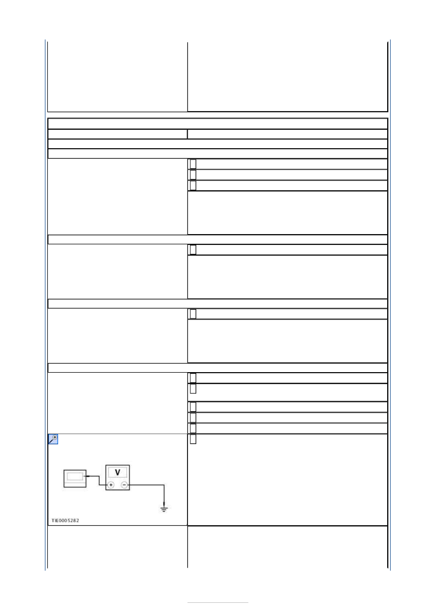
Measure the voltage between the heated rear 
window grid wire CC4RD02-A pin 1, circuit CRD06C 

(BN/YE), harness side and ground. 

Is the voltage greater than 10 volts? 
Yes 

GO to D5

.  

No 


GO to D13

.  

D5: CHECK THE HEATED REAR WINDOW GRID GROUND CIRCUIT

Ignition switch in position 0. 

Disconnect Heated Rear Window Grid Wires 
C4RD02-B. 

Measure the resistance between the heated rear 
window C4RD02-B pin 1, circuit GD150AE 

(BK/WH), harness side and ground.  

Is the resistance less than 5 ohms? 
Yes 

CARRY OUT the Heated Rear Window Grid Wire 
Component Test in this procedure. TEST the system 
for normal operation.  

No 

REPAIR circuit GD150AE (BK/WH). TEST the system 
for normal operation.  

D6: CHECK THE OPERATION OF THE HEATED WINDSHIELD SWITCH LED

Operate the heated windshield switch.  

Does the heated windshield switch ON LED illuminate?  
Yes 

GO to D7

.  

No 

GO to D16

.  

D7: CHECK FOR VOLTAGE TO THE HEATED WINDSHIELD GRID WIRES

Ignition switch in position 0. 

Disconnect Heated Windshield Grid Wires C2RD03 
and C2RD04-A. 

Ignition switch in position III. 

Ignition switch in position II. 

Operate the heated windshield control switch.  

Measure the voltage between the:  

heated windshield left-hand grid wire C2RD03 pin 
1, circuit CBB35A (YE/GY), harness side and 
ground.  
heated windshield right-hand grid wire C2RD04-A 
pin 1, circuit CBB34B (VT/BN), harness side and 
ground.  

Is the voltage greater than 10 volts? 
Yes 

GO to D8

.  

No 

GO to D18

.  

D8: CHECK THE HEATED WINDSHIELD GRID WIRE GROUND CIRCUITS

Ignition switch in position 0. 

Measure the resistance between the heated 
windshield ground circuits and ground.  


Are the resistances less than 5 ohms? 
Yes 

GO to D9

.  

No 

REPAIR the heated windshield ground circuit(s). 
TEST the system for normal operation.  

D9: CHECK THE HEATED WINDSHIELD GRID WIRES

Measure the resistance between the:  

heated windshield left-hand grid wire C2RD03 pin 
1, circuit CBB35A (YE/GY), harness side and 
ground.  
heated windshield right-hand grid wire C2RD04-A 
pin 1, circuit CBB34B (VT/BN), harness side and 
ground.  

Are the resistances greater than 10,000 ohms? 
Yes 

INSTALL a new windshield glass.  
REFER to: Windshield Glass (501-11 Glass, Frames 
and Mechanisms, Removal and Installation). 
TEST the system for normal operation.  

No 

VERIFY the customer concern.  

D10: CHECK THE HEATED REAR WINDOW SWITCH GROUND CIRCUIT

Ignition switch in position 0. 

Disconnect Heated Rear Window Switch C2RD09-B. 

Measure the resistance between the heated rear 
window switch C2RD09-B pin 4, circuit GD133BN 

(BK), harness side and ground.  

Is the resistance less than 5 ohms? 
Yes 

GO to D11

.  

No 

REPAIR circuit GD133BN (BK). TEST the system for 
normal operation.  

D11: CHECK FOR CONTINUITY BETWEEN THE CENTRAL JUNCTION BOX (CJB) AND 
THE HEATED REAR WINDOW SWITCH LED

Disconnect CJB C1BP02-C. 

Measure the resistance between the CJB C1BP02-C 
pin 46, circuit CRD04A (BN/GN), harness side and 

the heated rear window control switch C2RD09-B 
pin 3, circuit CRD04A (BN/GN), harness side.  

Is the resistance less than 5 ohms? 


Yes 

GO to D12

.  

No 

Repair circuit CRD04A (BN/GN). TEST the system 
for normal operation.  

D12: CHECK FOR CONTINUITY BETWEEN THE CENTRAL JUNCTION BOX (CJB) AND 
THE HEATED REAR WINDOW SWITCH

Measure the resistance between the CJB C1BP02-C 
pin 7, circuit CRD09A (BU/GY), harness side and 

the heated rear window control switch C2RD09-B 
pin 6, circuit CRD09A (BU/GY), harness side.  

Is the resistance less than 5 ohms? 
Yes 

CARRY OUT the CJB self-test. REFER to WDS. 
CARRY OUT the Heated Rear Window Glass Switch 
component test. REFER to the Wiring Diagrams. 

No 

Repair circuit CRD09A (BU/GY). TEST the system 
for normal operation.  

D13: CHECK FOR VOLTAGE TO THE HEATED REAR WINDOW RELAY

Ignition switch in position 0. 

Disconnect Heated Rear Window Relay RA2. 

Measure the voltage between the heated rear 
window relay RA2 pin 1 circuit SBB19F (BU/RD), 

harness side and ground.  

Is the voltage greater than 10 volts? 
Yes 

GO to D14

.  

No 

REPAIR circuit SBB19F (BU/RD). TEST the system 
for normal operation.  

D14: CHECK FOR CONTINUITY BETWEEN THE CJB AND THE HEATED REAR WINDOW 
RELAY

Disconnect CJB C1BP02-B. 

Measure the resistance between the CJB C1BP02-B 
pin 26, circuit CRD02A (BN/BU), harness side and 

the heated rear window relay RA2 pin 2, circuit 
CRD02A (BN/BU), harness side.  

Is the resistance less than 5 ohms? 


Content   ..  917  918  919  920   ..