Ford Galaxy / Ford S-MAX. Manual - part 916
 

  Index      Ford     Ford Galaxy / Ford S-MAX - service repair manual 2006 year


Search            


Content   ..  914  915  916  917   ..


Ford Galaxy / Ford S-MAX. Manual - part 916


Glass, Frames and Mechanisms - Glass, 
Frames and Mechanisms

S-MAX/Galaxy 2006.5 (02/2006-)


Print


Diagnosis and Testing 

Principles of Operation 

Inspection and Verification 

1. 1. Verify the customer concern. 

2. 2. Visually inspect for obvious signs of mechanical or electrical damage. 

Visual Inspection Chart 

3. 3. If an obvious cause for an observed or reported concern is found, correct the cause 

(if possible) before proceeding to the next step 

4. 4. If the cause is not visually evident, verify the symptom and refer to the Symptom 

Chart. 

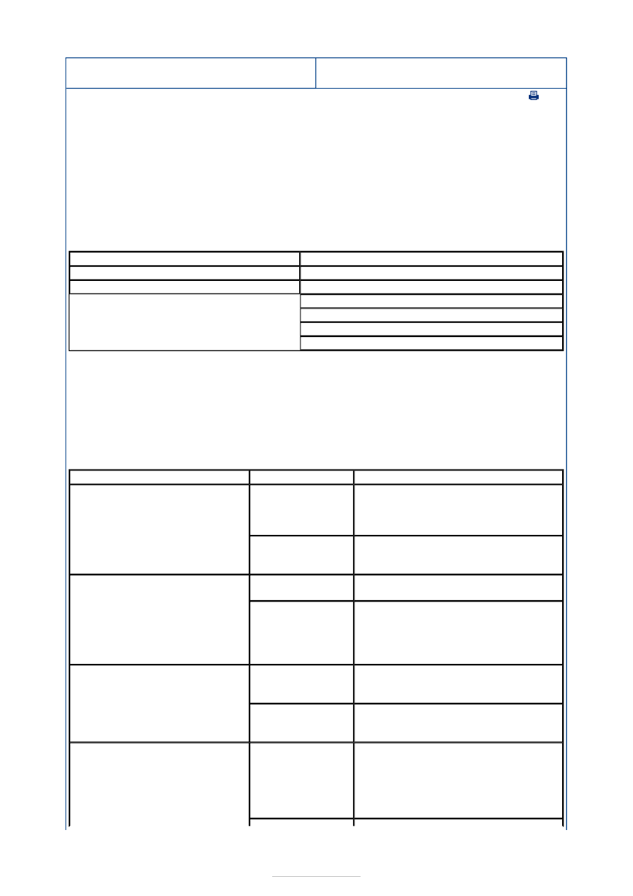
Symptom Chart 

Mechanical

Electrical

Window seal

Fuse(s)

Door window frame 

Door module(s)

Electrical connector(s)

Switch(es)

Grid wire(s)

Circuit(s)

Symptom

Possible Sources

Action

A single power window is 
inoperative - Driver side

Driver side front 

door switch. 

Door module.  
LIN bus. 

*

*
*

REFER to WDS.  

*

Door window 

regulator motor. 

Circuit(s). 

*

*

GO to Pinpoint Test 

A. 


*

A single power window is 
inoperative - Passenger side

Door module.  
LIN bus. 

*
*

REFER to WDS.  

*

Passenger power 

window switch.  

Door window 

regulator motor. 

Circuit(s). 

*

*

*

GO to Pinpoint Test 

B. 


*

The one-touch down feature is 
inoperative

Driver side front 

door switch. 

Door module.  

*

*

REFER to WDS.  

*

Passenger power 

window switch.  

*

CARRY OUT the Passenger Power 

Window Switch component test. 
REFER to the Wiring Diagrams. 

*

The defrost system is inoperative

Central junction 

box (CJB). 

Engine junction 

box (EJB). 

Rear junction 

box (RJB). 

*

*

*

REFER to WDS. 

*

Pinpoint Tests 

Heated 

windshield glass 
switch. 

*

CARRY OUT the Heated Windshield 

Glass Switch component test. REFER 
to the Wiring Diagrams. 

*

Heated rear 

window glass 
switch. 

*

CARRY OUT the Heated Rear Window 

Glass Switch component test. REFER 
to the Wiring Diagrams. 

*

Heated rear 

window grid 
wire. 

*

CARRY OUT the Heated Rear Window 

Grid Wire component test in this 
procedure. 

*

Heated 

windshield grid 
wire. 

Circuit(s) 

*

*

GO to Pinpoint Test 

D. 


*

The defrost system will not shut 
off automatically

Central junction 

box (CJB). 

*

REFER to WDS. 

*

Circuit(s) 

*

GO to Pinpoint Test 

E. 


*

The global open/closing function is 
inoperative/does not operate 
correctly

Central junction 

box (CJB). 

LIN bus. 

*

*

REFER to WDS. 

*

PINPOINT TEST A : A SINGLE POWER WINDOW IS INOPERATIVE - DRIVER 
SIDE 

TEST CONDITIONS

DETAILS/RESULTS/ACTIONS

A1: CHECK THE DRIVER SIDE FRONT DOOR SWITCH 

Ignition switch in position II. 

Operate the power mirror switch.  

Do the power mirrors operate?  
Yes 

GO to A2

.  

No 

GO to A8

.  

A2: CHECK FOR CONTINUITY BETWEEN THE DRIVER DOOR MODULE AND THE DRIVER 
SIDE FRONT DOOR WINDOW REGULATOR MOTOR - DOWN CIRCUIT 

NOTE: Use a digital multimeter for all electrical measurements. 

Ignition switch in position 0. 

Disconnect Driver Door Module C5PL01-A. 

Disconnect Driver Door Window Regulator Motor 
C5PW11. 

Measure the resistance between the driver door 
module C5PL01-A pin 1, circuit CPW35A (GN), 

harness side and the driver side front door window 
regulator motor C5PW11 pin 5, circuit CPW35B (GN), 
harness side. 

Is the resistance less than 5 ohms? 
Yes 

GO to A3

.  

No 

REPAIR circuit CPW35A (GN) or circuit CPW35B (GN). 
TEST the system for normal operation.  

A3: CHECK FOR CONTINUITY BETWEEN THE DRIVER DOOR MODULE AND THE DRIVER 


SIDE FRONT DOOR WINDOW REGULATOR MOTOR - UP CIRCUIT 

Measure the resistance between the driver door 
module C5PL01-A pin 12, circuit CPW34A (BU), 

harness side and the driver side front door window 
regulator motor C5PW11 pin 6, circuit CPW34B (BU), 
harness side. 

Is the resistance less than 5 ohms? 
Yes 

GO to A4

.  

No 

REPAIR circuit CPW34A (BU) or circuit CPW34B (BU). 
TEST the system for normal operation.  

A4: CHECK FOR CONTINUITY BETWEEN THE DRIVER DOOR MODULE AND THE DRIVER 
SIDE FRONT DOOR WINDOW REGULATOR MOTOR - HALL SENSOR SUPPLY CIRCUIT 

Measure the resistance between the driver door 
module C5PL01-A pin 17, circuit LPW36A (WH/BN), 

harness side and the driver side front door window 
regulator motor C5PW11 pin 2, circuit LPW36B 
(WH/BN), harness side. 

Is the resistance less than 5 ohms? 
Yes 

GO to A5

.  

No 

REPAIR circuit LPW36A (WH/BN) or circuit LPW36B 
(WH/BN). TEST the system for normal operation.  

A5: CHECK FOR CONTINUITY BETWEEN THE DRIVER DOOR MODULE AND THE DRIVER 
SIDE FRONT DOOR WINDOW REGULATOR MOTOR - HALL SENSOR GROUND CIRCUIT 

Measure the resistance between the driver door 
module C5PL01-A pin 16, circuit RPW37A (VT/GN), 

harness side and the driver side front door window 
regulator motor C5PW11 pin 1, circuit RPW37B 
(VT/GN), harness side. 

Is the resistance less than 5 ohms? 
Yes 

GO to A6

.  

No 

REPAIR circuit RPW37A (VT/GN) or circuit RPW37B 
(VT/GN). TEST the system for normal operation.  

A6: CHECK FOR CONTINUITY BETWEEN THE DRIVER DOOR MODULE AND THE DRIVER 
SIDE FRONT DOOR WINDOW REGULATOR MOTOR - HALL SENSOR 1 CIRCUIT 

Measure the resistance between the driver door 
module C5PL01-A pin 6, circuit VPW38A (YE/BU), 

harness side and the driver side front door window 
regulator motor C5PW11 pin 3, circuit VPW38B 


(YE/BU), harness side. 

Is the resistance less than 5 ohms? 
Yes 

GO to A7

.  

No 

REPAIR circuit VPW38A (YE/BU) or circuit VPW38B 
(YE/BU). TEST the system for normal operation.  

A7: CHECK FOR CONTINUITY BETWEEN THE DRIVER DOOR MODULE AND THE DRIVER 
SIDE FRONT DOOR WINDOW REGULATOR MOTOR - HALL SENSOR 2 CIRCUIT 

Measure the resistance between the driver door 
module C5PL01-A pin 5, circuit VPW39A (BU/WH), 

harness side and the driver side front door window 
regulator motor C5PW11 pin 4, circuit VPW39B 
(BU/WH), harness side. 

Is the resistance less than 5 ohms? 
Yes 

Install a new driver side front door window regulator 
motor.  
REFER to: Door Window Regulator Motor (501-11 
Glass, Frames and Mechanisms, Removal and 
Installation). 
TEST the system for normal operation.  

No 

REPAIR circuit VPW39A (BU/WH) or circuit VPW39B 
(BU/WH). TEST the system for normal operation.  

A8: CHECK FOR CONTINUITY BETWEEN THE DRIVER SIDE FRONT DOOR SWITCH AND 
GROUND

Ignition switch in position 0. 

Disconnect Driver Side Front Door Switch C5PL22. 

Measure the resistance between the driver side front 
door switch C5PL22 pin 4, circuit GD135H (BK/GY), 

harness side and ground. 

Is the resistance less than 5 ohms? 
Yes 

GO to A9

.  

No 

REPAIR circuit GD135H (BK/GY). TEST the system for 
normal operation.  


Content   ..  914  915  916  917   ..