Ford Galaxy / Ford S-MAX. Manual - part 875
 

  Index      Ford     Ford Galaxy / Ford S-MAX - service repair manual 2006 year


Search            


Content   ..  873  874  875  876   ..


Ford Galaxy / Ford S-MAX. Manual - part 875


GO to E4

.  

No 

LOCATE and REPAIR the break in circuit CPL02A (BK) 
between the driver door module and the driver door 
lock with the aid of the Wiring Diagrams. CHECK the 
operation of the system. 

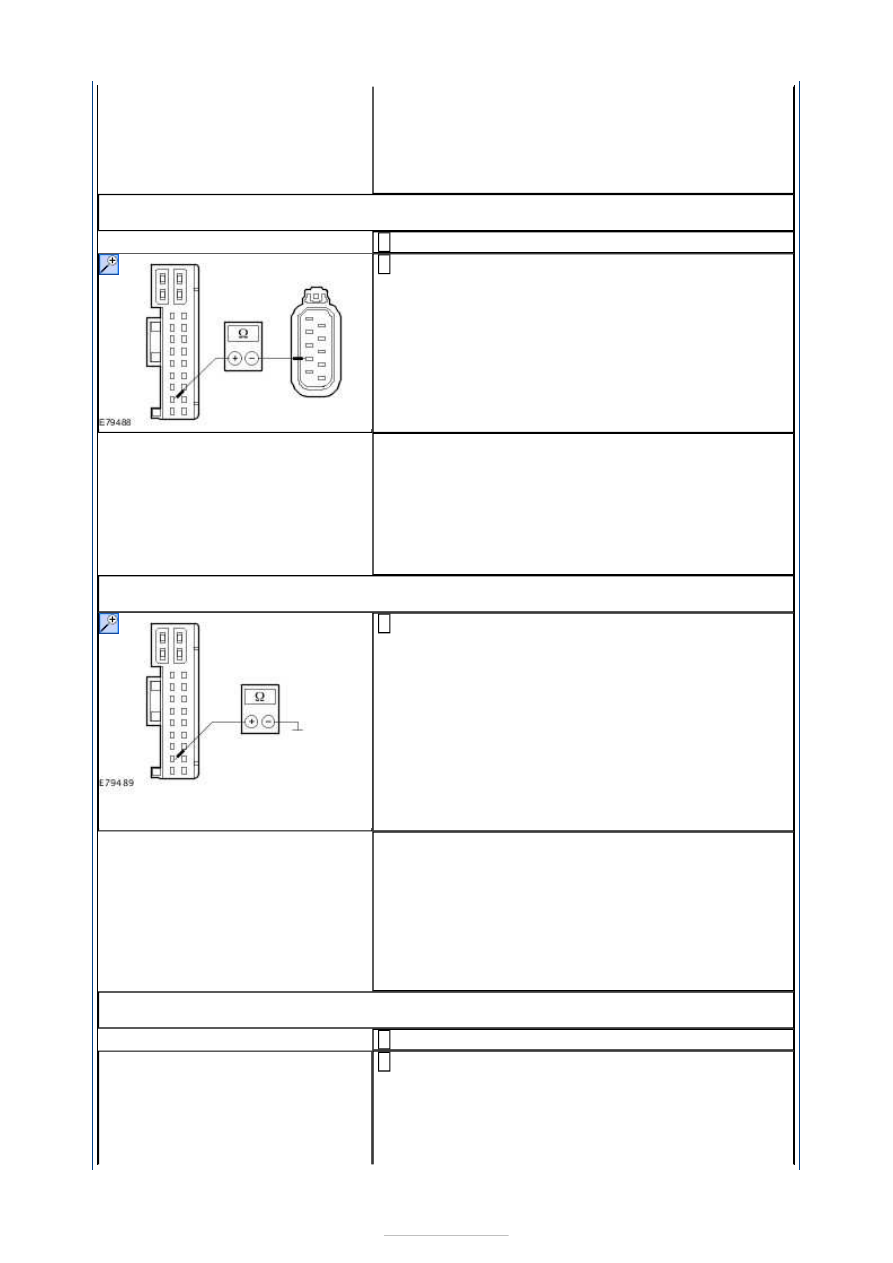
E3: CHECK FOR A BREAK IN THE CIRCUIT BETWEEN THE DRIVER DOOR MODULE AND 
THE DRIVER DOOR LOCK

Ignition switch in position 0. 

Measure the resistance between the driver door 
module connector C5PL01-A pin 10, circuit CPL02AA 

(BK), wiring harness side and the driver door lock 
connector C5PL63 pin 5, circuit CPL02AA (BK), wiring 
harness side. 

Is a resistance of less than 2 Ohm measured? 
Yes 

GO to E4

.  

No 

LOCATE and REPAIR the break in circuit CPL02AA 
(BK) between the driver door module and the driver 
door lock with the aid of the Wiring Diagrams. CHECK 
the operation of the system. 

E4: CHECK FOR SHORT TO GROUND BETWEEN THE DRIVER DOOR MODULE AND THE 
DRIVER DOOR LOCK

Measure the resistance between:  

the driver door module connector C5PL01-A pin 10, 
circuit CPL02A (BK), wiring harness side and 
ground (LHD).  
or  
the driver door module connector C5PL01-A pin 10, 
circuit CPL02AA (BK), wiring harness side and 
ground (RHD). 

Is a resistance of more than 10,000 ohms measured? 
Yes 

LHD vehicles:

GO to E5

.  

RHD vehicles:

GO to E7

.  

No 

LOCATE and REPAIR the short to ground in the circuit 
between the driver door module and the driver door 
lock with the aid of the Wiring Diagrams. CHECK the 
operation of the system. 

E5: CHECK THE VOLTAGE AT THE DRIVER DOOR LOCK (DURING 
LOCKING/UNLOCKING

Connect driver door module C5PL01-A. 

Measure the voltage between the driver door lock 
connector C5PL63 pin 7, circuit CPL02A (BK), wiring 

harness side and ground. 


Lock and unlock the vehicle with the key in the door 
lock cylinder. 

Is battery voltage measured during unlocking? 
Yes 

GO to E6

.  

No 

CHECK and if necessary INSTALL a new driver door 
module. CHECK the operation of the system. 

E6: CHECK THE VOLTAGE AT THE DRIVER DOOR LOCK (DURING DOUBLE 
LOCKING/UNLOCKING)

Measure the voltage between the driver door lock 
connector C6PL63 pin 7, circuit CPL02A (BK), wiring 

harness side and ground. 

Double lock and unlock the vehicle with the key in 
the door lock cylinder. 

Is battery voltage measured during unlocking? 
Yes 

CHECK and if necessary INSTALL a new driver door 
lock. CHECK the operation of the system. 

No 

CHECK and if necessary INSTALL a new driver door 
module. CHECK the operation of the system. 

E7: CHECK THE VOLTAGE AT THE DRIVER DOOR LOCK (DURING 
LOCKING/UNLOCKING)

Connect driver door module C5PL01-A. 

Measure the voltage between the driver door lock 
connector C5PL63 pin 5, circuit CPL02AA (BK), wiring 

harness side and ground. 

Lock and unlock the vehicle with the key in the door 
lock cylinder. 

Is battery voltage measured during unlocking? 
Yes 

GO to E8

.  

No 

CHECK and if necessary INSTALL a new driver door 


module. CHECK the operation of the system. 

E8: CHECK THE VOLTAGE AT THE DRIVER DOOR LOCK (DURING DOUBLE 
LOCKING/UNLOCKING)

Measure the voltage between the driver door lock 
connector C5PL63 pin 5, circuit CPL02AA (BK), wiring 

harness side and ground. 

Double lock and unlock the vehicle with the key in 
the door lock cylinder. 

Is battery voltage measured during unlocking? 
Yes 

CHECK and if necessary INSTALL a new driver door 
lock. CHECK the operation of the system. 

No 

CHECK and if necessary INSTALL a new driver door 
module. CHECK the operation of the system. 

PINPOINT TEST F : CIRCUIT OF THE PASSENGER CENTRAL LOCKING 
MOTOR WITH DOUBLE LOCKING FAULTY. 

WARNING: The window anti-trap function will not operate during the window motor 

initialization procedure. 
NOTE: If the power to a window regulator motor has been disconnected, it is necessary 
to initialize that window regulator motor.  

TEST CONDITIONS

DETAILS/RESULTS/ACTIONS

F1: CHECK FOR SHORT TO VOLTAGE BETWEEN THE PASSENGER DOOR MODULE AND 
THE PASSENGER DOOR LOCK

Disconnect passenger door module C6PL01-A. 

Disconnect passenger door lock C6PL64. 

Ignition switch in position II. 

Measure the voltage between:  

the passenger door module connector C6PL01-A 
pin 10, circuit CPL65A (BK), wiring harness side 
and ground (LHD).  
or  
the passenger door module connector C6PL01-A 
pin 10, circuit CPL65AA (BK), wiring harness side 
and ground (RHD). 

Is a voltage measured? 
Yes 

LOCATE and REPAIR the short to voltage in the 
circuit between the passenger door module and the 
passenger door lock with the aid of the Wiring 
Diagrams. CHECK the operation of the system. 

No 

LHD vehicles:

GO to F2

.  

RHD vehicles:

GO to F3

.  

F2: CHECK FOR A BREAK IN THE CIRCUIT BETWEEN THE PASSENGER DOOR MODULE 


AND THE PASSENGER DOOR LOCK

Ignition switch in position 0. 

Measure the resistance between the passenger door 
module connector C6PL01-A pin 10, circuit CPL65A 

(BK), wiring harness side and the passenger door 
lock connector C6PL64 pin 5, circuit CPL65A (BK), 
wiring harness side. 

Is a resistance of less than 2 Ohm measured? 
Yes 

GO to F4

.  

No 

LOCATE and REPAIR the break in circuit CPL65A (BK) 
between the passenger door module and the 
passenger door lock with the aid of the Wiring 
Diagrams. CHECK the operation of the system. 

F3: CHECK FOR A BREAK IN THE CIRCUIT BETWEEN THE PASSENGER DOOR MODULE 
AND THE PASSENGER DOOR LOCK

Ignition switch in position 0. 

Measure the resistance between the passenger door 
module connector C6PL01-A pin 10, circuit CPL65AA 

(BK), wiring harness side and the passenger door 
lock connector C6PL64 pin 7, circuit CPL65AA (BK), 
wiring harness side. 

Is a resistance of less than 2 Ohm measured? 
Yes 

GO to F4

.  

No 

LOCATE and REPAIR the break in circuit CPL65AA 
(BK) between the passenger door module and the 
passenger door lock with the aid of the Wiring 
Diagrams. CHECK the operation of the system. 

F4: CHECK FOR SHORT TO GROUND BETWEEN THE PASSENGER DOOR MODULE AND 
THE PASSENGER DOOR LOCK

Ignition switch in position 0. 

Measure the resistance between:  

the passenger door module connector C6PL01-A, 
pin 10, circuit CPL65A (BK), wiring harness side 
and ground.  
or  
the passenger door module connector C6PL01-A 
pin 10, circuit CPL65AA (BK), wiring harness side 
and ground. 

Is a resistance of more than 10,000 ohms measured? 
Yes 


Content   ..  873  874  875  876   ..