Ford Galaxy / Ford S-MAX. Manual - part 825
 

  Index      Ford     Ford Galaxy / Ford S-MAX - service repair manual 2006 year


Search            


Content   ..  823  824  825  826   ..


Ford Galaxy / Ford S-MAX. Manual - part 825


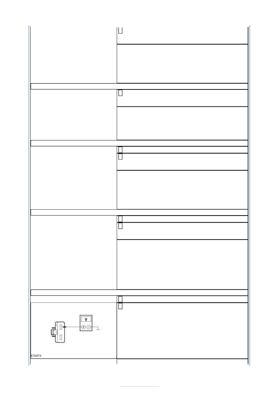
Measure the voltage between relay DC21, socket 
C1BB01A pin 107, circuit CDC01A (GN/VT), wiring 

harness side and ground. 

Does the meter display battery voltage? 
Yes 

GO to AF9

.  

No 

LOCATE and REPAIR the break in the circuit between 
relay DC21 and the CJB using the Wiring Diagrams. 
CHECK the operation of the system. 

AF9: CHECK THE VOLTAGE AT RELAY DC21 

Measure the voltage between relay DC21, socket 
C1BB01A, pin 104, circuit SDC02H (RD), wiring 

harness side and ground. 

Does the meter display battery voltage? 
Yes 

GO to AF10

.  

No 

CHECK and if necessary RENEW the EJB. CHECK the 
operation of the system. 

AF10: CHECK THE CIRCUIT BETWEEN RELAY DC21 AND FUSE F41 FOR OPEN CIRCUIT

Ignition switch in position 0. 

Measure the resistance between relay DC21, socket 
C1BB01A, pin 105, circuit CDC21F (GY/BN), wiring 

harness side and fuse F42. 

Is a resistance of less than 2 Ohms registered? 
Yes 

GO to AF11

.  

No 

LOCATE and REPAIR the break in the circuit between 
relay DC21 and fuse F41 using the Wiring Diagrams. 
CHECK the operation of the system. 

AF11: CHECK THE GROUND CONNECTION OF DC21 

Ignition switch in position 0. 

Measure the resistance between DC21, connector 
C1BB01-A, pin 106, circuit GD120P (BK/GN), wiring 

harness side and ground. 

Is a resistance of less than 2 Ohms registered? 
Yes 

RENEW relay DC21. CHECK the operation of the 
system. 

No 

LOCATE and RECTIFY the break in the corresponding 
circuit between DC21 and soldered connection SP358 
with the aid of the Wiring Diagrams. CHECK the 
operation of the system. 

AF12: CHECK THE VOLTAGE AT THE GEM

Disconnect Connector C1BP02-G from the GEM. 

Measure the voltage between the GEM, connector 
C1BP02-G, pin 1, circuit SBB17A (RD), wiring 

harness side and ground. 


Does the meter display battery voltage? 
Yes 

GO to AF14

.  

No 

GO to AF13

.  

AF13: CHECK FOR OPEN CIRCUIT BETWEEN THE CJB AND THE EJB

Disconnect Connector C1BB03-G from the EJB. 

Measure the resistance between the CJB, connector 
C1BP02-G, pin 1, circuit SBB17A (RD), wiring 

harness side and the EJB, connector C1BB03-G, pin 
1, circuit SBB17A (RD), wiring harness side. 

Is a resistance of less than 2 Ohms registered? 
Yes 

CHECK and if necessary RENEW the EJB. CHECK the 
operation of the system. 

No 

LOCATE and RECTIFY the break in circuit SBB17A 
(RD) between the EJB and the CJB with the aid of the 
Wiring Diagrams. CHECK the operation of the 
system. 

AF14: CHECK THE VOLTAGE AT THE GEM

Measure the voltage between the GEM, connector 
C1BP02-G, pin 2, circuit SBB18A (YE), wiring 

harness side and ground. 

Does the meter display battery voltage? 
Yes 

GO to AF16

.  

No 

GO to AF15

.  

AF15: CHECK FOR OPEN CIRCUIT BETWEEN THE CJB AND THE EJB

Disconnect Connector C1BP03-H from the EJB. 

Measure the resistance between the CJB, connector 
C1BP02-G, pin 2, circuit SBB18A (YE), wiring 

harness side and the EJB, connector C1BB03-H, pin 
1, circuit SBB18A (YE), wiring harness side. 

Is a resistance of less than 2 Ohms registered? 
Yes 

CHECK and if necessary RENEW the EJB. CHECK the 
operation of the system. 

No 

LOCATE and RECTIFY the break in circuit SBB18A 
(YE) between the GEM and the EJB with the aid of 
the Wiring Diagrams. CHECK the operation of the 
system. 

AF16: CHECK THE VOLTAGE AT THE GEM

Disconnect Connector C1BP02-A from the GEM. 

Ignition switch in position II. 

Measure the voltage between the GEM, connector 
C1BP02-A, pin 65, circuit CBB41A (BU), wiring 

harness side and ground. 

Does the meter display battery voltage? 


Yes 

GO to AF18

.  

No 

GO to AF17

.  

AF17: CHECK FOR OPEN CIRCUIT BETWEEN THE CJB AND THE EJB

Ignition switch in position 0. 

Disconnect Connector C1BB01-A from the EJB. 

Measure the resistance between the CJB, connector 
C1BP02-A, pin 65, circuit CBB41A (BU), wiring 

harness side and the EJB, connector C1BB01-A, pin 
98, circuit CBB41A (BU), wiring harness side. 

Is a resistance of less than 2 Ohms registered? 
Yes 

CHECK and if necessary RENEW the EJB. CHECK the 
operation of the system. 

No 

LOCATE and RECTIFY the break in circuit CBB41A 
(BU) between the EJB and the CJB with the aid of the 
Wiring Diagrams. CHECK the operation of the 
system. 

AF18: TEST THE GEM GROUND CONNECTION

Ignition switch in position 0. 

Measure the resistance between the GEM, connector 
C1BP02-A, pin 54, circuit GD123F (BK/GY), wiring 

harness side and ground. 

Is a resistance of less than 2 Ohms registered? 
Yes 

GO to AF19

.  

No 

LOCATE and REPAIR the break in circuit GD123F 
(BK/GY) between the GEM and ground connection 
GD123 with the aid of the Wiring Diagrams. CHECK 
the operation of the system. 

AF19: TEST THE GEM GROUND CONNECTION

Disconnect Connector C1BP02-B from the GEM. 

Measure the resistance between the GEM, connector 
C1BP02-B, pin 65, circuit GD134U (BK/VT), wiring 

harness side and ground. 

Is a resistance of less than 2 Ohms registered? 
Yes 

GO to AF20

.  

No 

LOCATE and REPAIR the break in circuit GD134U 
(BK/VT) between the GEM and ground connection 


GD134 with the aid of the Wiring Diagrams. CHECK 
the operation of the system. 

AF20: CHECK FOR OPEN CIRCUIT BETWEEN THE GEM AND THE DATA LINK 
CONNECTOR (DLC)

CAUTION: The following measurement must only be performed using the Ford 

approved diagnostic tool digital multimeter. Failure to observe this instruction can lead to 
damage. 

Measure the resistance between the GEM, connector 
C1BP02-A, pin 50, circuit VDB07J (VT/OG), wiring 

harness side and the DLC, connector C3DB04, pin 
11, circuit VDB07D (GY/OG), wiring harness side. 

Is a resistance of less than 2 Ohms registered? 
Yes 

GO to AF21

.  

No 

LOCATE and REPAIR the break in the circuit between 
the GEM and the DLC using the Wiring Diagrams. 
CHECK the operation of the system. 

AF21: CHECK FOR OPEN CIRCUIT BETWEEN THE GEM AND THE DLC

CAUTION: The following measurement must only be performed using the Ford 

approved diagnostic tool digital multimeter. Failure to observe this instruction can lead to 
damage. 

Measure the resistance between the GEM, connector 
C1BP02-A, pin 49, circuit VDB06AC (GY/OG), wiring 

harness side and the DLC, connector C3DB04, pin 3, 
circuit VDB06X (GY/OG), wiring harness side. 

Is a resistance of less than 2 Ohms registered? 
Yes 

GO to AF22

.  

No 

LOCATE and REPAIR the break in the circuit between 
the GEM and the DLC using the Wiring Diagrams. 
CHECK the operation of the system. 

AF22: CHECK FOR OPEN CIRCUIT BETWEEN THE GEM AND THE DATA LINK 
CONNECTOR (DLC)

CAUTION: The following measurement must only be performed using the Ford 

approved diagnostic tool digital multimeter. Failure to observe this instruction can lead to 
damage. 

Disconnect Connector C1BP02-C from the GEM. 

Measure the resistance between the GEM, connector 
C1BP02-C, pin 47, circuit VDB04Y (WH/BU), wiring 

harness side and the DLC, connector C3DB04, pin 6, 
circuit VDB04L (WH/BU), wiring harness side. 


Content   ..  823  824  825  826   ..