Ford Galaxy / Ford S-MAX. Manual - part 822
 

  Index      Ford     Ford Galaxy / Ford S-MAX - service repair manual 2006 year


Search            


Content   ..  820  821  822  823   ..


Ford Galaxy / Ford S-MAX. Manual - part 822


ground. 

Does the meter display battery voltage? 
Yes 

GO to AC12

.  

No 

GO to AC14

.  

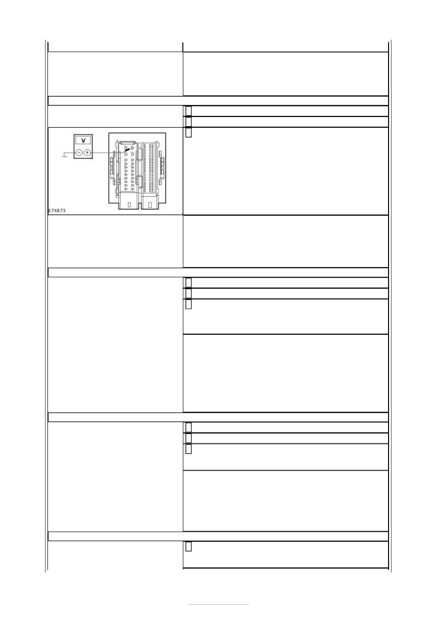
AC12: CHECK THE VOLTAGE AT THE CJB

Ignition switch in position 0. 

Disconnect CJB from socket C1BP02-A. 

Measure the voltage between the CJB, socket 
C1BP02-A, pin 65, circuit CBB41A (VT/GY), wiring 

harness side and ground. 

Does the meter display battery voltage? 
Yes 

CHECK the CJB and RENEW as necessary. CHECK the 
operation of the system. 

No 

GO to AC13

.  

AC13: CHECK FOR OPEN CIRCUIT BETWEEN THE CJB AND THE EJB

Ignition switch in position 0. 

Disconnect Connector C1BB01-A from the EJB. 

Measure the resistance between the CJB, connector 
C1BP02-A, pin 65, circuit CBB41A (VT/GY), wiring 

harness side and the EJB, connector C1BB01-A, pin 
98, circuit CBB41A (VT/GY), wiring harness side. 

Is a resistance of less than 2 Ohms registered? 
Yes 

CHECK and if necessary RENEW the EJB. CHECK the 
operation of the system. 

No 

LOCATE and REPAIR the break in circuit CBB41A 
(VT/GY) between the electronic stability program 
module and the CJB with the aid of the Wiring 
Diagrams. CHECK the operation of the system. 

AC14: CHECK THE VOLTAGE AT RELAY DC21 

Ignition switch in position 0. 

Disconnect Relay DC21 from socket C1BB01-A. 

Measure the voltage between relay DC21, socket 
C1BB01-A, pin 1, circuit CDC01A (GN/VT), wiring 

harness side and ground. 

Does the meter display battery voltage? 
Yes 

GO to AC15

.  

No 

LOCATE and REPAIR the break in the circuit between 
relay DC21 and the CJB using the Wiring Diagrams. 
CHECK the operation of the system. 

AC15: CHECK THE VOLTAGE AT RELAY DC21 

Measure the voltage between relay DC21, socket 
C1BB01-A, pin 3, circuit SDC02H (RD), wiring 

harness side and ground. 


Does the meter display battery voltage? 
Yes 

GO to AC16

.  

No 

CHECK and if necessary RENEW the EJB. CHECK the 
operation of the system. 

AC16: CHECK THE CIRCUIT BETWEEN RELAY DC21 AND FUSE F41 FOR OPEN CIRCUIT

Ignition switch in position 0. 

Measure the resistance between relay DC21, socket 
C1BB01-A, pin 105, circuit CDC21F (GY/BN), wiring 

harness side and fuse F41. 

Is a resistance of less than 2 Ohms registered? 
Yes 

GO to AC17

.  

No 

LOCATE and REPAIR the break in the circuit between 
relay DC21 and fuse F41 using the Wiring Diagrams. 
CHECK the operation of the system. 

AC17: CHECK THE GROUND CONNECTION OF DC21 

Ignition switch in position 0. 

Measure the resistance between DC21, connector 
C1BB01-A, pin 106, circuit GD120P (BK/GN), wiring 

harness side and ground. 

Is a resistance of less than 2 Ohms registered? 
Yes 

RENEW relay DC21. CHECK the operation of the 
system. 

No 

LOCATE and RECTIFY the break in the corresponding 
circuit between DC21 and soldered connection SP358 
with the aid of the Wiring Diagrams. CHECK the 
operation of the system. 

AC18: CHECK THE VOLTAGE AT THE EJB

Disconnect Connector C1BB01-B from the EJB. 

Measure the voltage between the EJB, connector 
C1BB01-B, pin 1, circuit SDC02A (RD), wiring 

harness side and ground. 

Does the meter display battery voltage? 
Yes 

CHECK and if necessary RENEW the EJB. CHECK the 
operation of the system. 

No 

LOCATE and RECTIFY the break in circuit SDC02A 
(RD) between the EJB and the battery with the aid of 
the Wiring Diagrams. CHECK the operation of the 
system. 

AC19: CHECK THE VOLTAGE AT THE ESP MODULE

Ignition switch in position 0. 

Disconnect Connector C1CA01 from the electronic 
stability program module. 

Measure the voltage between the ESP module, 
connector C1CA01, pin 1, circuit SBB26A (YE/RD), 

wiring harness side and ground. 

Does the meter display battery voltage? 
Yes 

GO to AC21

.  

No 

GO to AC20

.  

AC20: CHECK FOR OPEN CIRCUIT BETWEEN THE EJB AND THE ESP MODULE

Disconnect Connector C1BB01-A from the EJB. 

Measure the resistance between the EJB, connector 
C1BB01-A, pin 112, circuit SBB26A (YE/RD), wiring 

harness side and the ESP module, connector 
C1CA01, pin 1, circuit SBB26A (YE/RD), wiring 
harness side. 

Is a resistance of less than 2 Ohms registered? 
Yes 

CHECK and if necessary RENEW the EJB. CHECK the 
operation of the system. 

No 

LOCATE and RECTIFY the break in circuit SBB26A 
(YE/RD) between the ESP module and the EJB with 
the aid of the Wiring Diagrams. CHECK the operation 
of the system. 

AC21: CHECK THE VOLTAGE AT THE ESP MODULE

Measure the voltage between the ESP module, 
connector C1CA01, pin 25, circuit SBB25A (RD), 

wiring harness side and ground. 

Does the meter display battery voltage? 
Yes 

GO to AC27

.  

No 

GO to AC22

.  

AC22: CHECK FOR OPEN CIRCUIT BETWEEN THE EJB AND THE ESP MODULE

Disconnect Connector C1BB01-A from the EJB. 

Measure the resistance between the EJB, connector 
C1BB01-A, pin 113, circuit SBB25AB (RD), wiring 

harness side and the ESP module, connector 
C1CA01, pin 25, circuit SBB25A (RD), wiring harness 
side. 

Is a resistance of less than 2 Ohms registered? 
Yes 

CHECK and if necessary RENEW the EJB. CHECK the 
operation of the system. 

No 

LOCATE and REPAIR the break in the circuit between 
the electronic stability program module and the EJB 
using the Wiring Diagrams. CHECK the operation of 
the system. 

AC23: CHECK THE VOLTAGE AT THE ESP MODULE

Measure the voltage between the ESP module, 
connector C1CA01, pin 7, circuit SBB36A (GN/RD), 

wiring harness side and ground. 

Does the meter display battery voltage? 
Yes 

GO to AC25

.  

No 

GO to AC24

.  

AC24: CHECK FOR OPEN CIRCUIT BETWEEN THE EJB AND THE ESP MODULE

Disconnect Connector C1BB01-A from the EJB. 

Measure the resistance between the EJB, connector 
C1BB01-A, pin 41, circuit SBB36AB (GN/RD), wiring 

harness side and the ESP module, connector 
C1CA01, pin 7, circuit SBB36A (GN/RD), wiring 
harness side. 

Is a resistance of less than 2 Ohms registered? 

Yes 

CHECK and if necessary RENEW the EJB. CHECK the 
operation of the system. 

No 

LOCATE and REPAIR the break in the circuit between 
the electronic stability program module and the EJB 
using the Wiring Diagrams. CHECK the operation of 
the system. 

AC25: CHECK THE VOLTAGE AT THE ESP MODULE

Ignition switch in position II. 

Measure the voltage between the ESP module, 
connector C1CA01, pin 33, circuit CBP03A (GY), 

wiring harness side and ground. 

Does the meter display battery voltage? 
Yes 

GO to AC27

.  

No 

GO to AC26

.  

AC26: CHECK FOR OPEN CIRCUIT BETWEEN THE CJB AND THE ESP MODULE

Ignition switch in position 0. 

Disconnect Connector C1BP02-A from the CJB. 

Measure the resistance between the CJB, connector 
C1BP02-A, pin 55, circuit CBP03AB (GY), wiring 

harness side and the ESP module, connector 
C1CA01, pin 33, circuit CBP03A (GY), wiring harness 
side. 

Is a resistance of less than 2 Ohms registered? 
Yes 

CHECK the CJB and RENEW as necessary. CHECK the 
operation of the system. 

No 

LOCATE and REPAIR the break in the circuit between 
the electronic stability program module and the CJB 
using the Wiring Diagrams. CHECK the operation of 
the system. 

AC27: CHECK THE GROUND CONNECTION OF THE ELECTRONIC STABILITY PROGRAM 
MODULE

Ignition switch in position 0. 

Measure the resistance between the ESP module, 
connector C1CA01, pin 38, circuit GD122X (BK), 

wiring harness side and ground. 

Measure the resistance between the ESP module, 
connector C1CA01, pin 13, circuit GD122V (BK), 

wiring harness side and ground. 

Is a resistance of less than 2 Ohm measured in both 
cases? 
Yes 

GO to AC28

.  

No 

- If a resistance of more than 2 Ohms is measured in 
one of the measurements:LOCATE and REPAIR the 
break in the relevant circuit between the ESP module 
and soldered connection SP200 with the aid of the 
Wiring Diagrams. CHECK the operation of the 
system. 
- If a resistance of more than 2 Ohms is measured in 
both of the measurements:LOCATE and REPAIR the 
break in circuit GD122Y (BK) between soldered 
connection SP200 and ground connection G1D130C 


Content   ..  820  821  822  823   ..