Ford Galaxy / Ford S-MAX. Manual - part 820
 

  Index      Ford     Ford Galaxy / Ford S-MAX - service repair manual 2006 year


Search            


Content   ..  818  819  820  821   ..


Ford Galaxy / Ford S-MAX. Manual - part 820


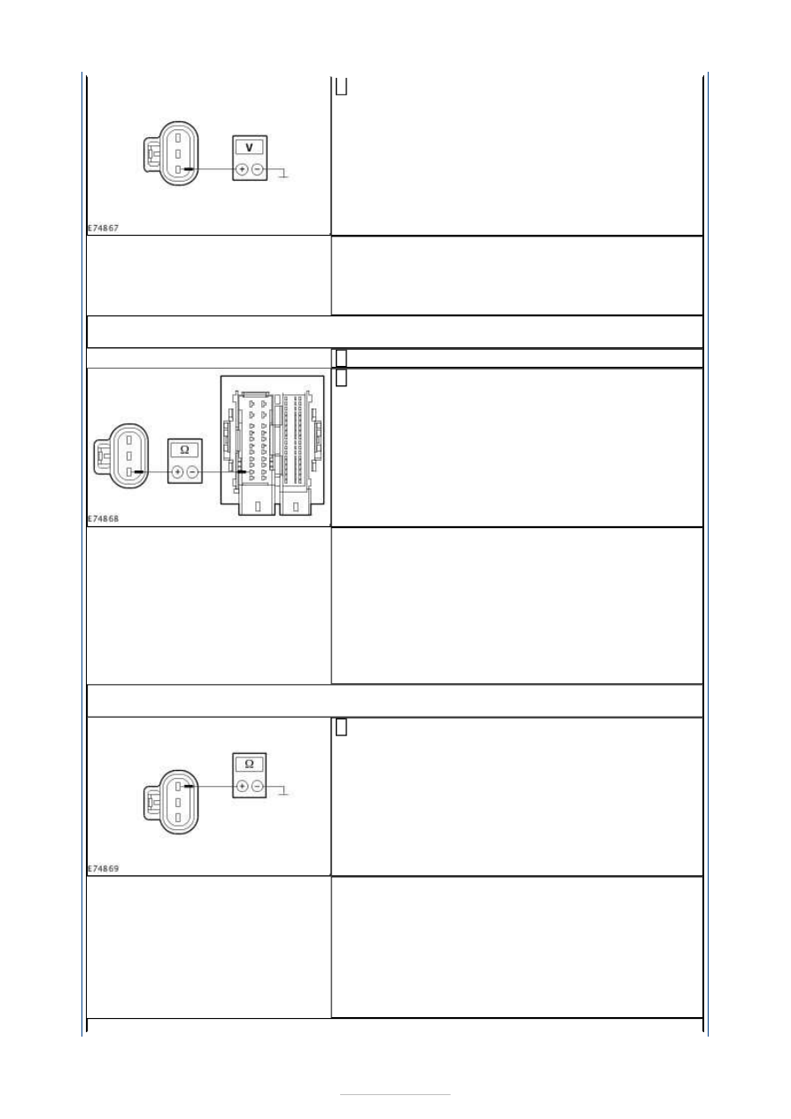
Measure the voltage between the anti-theft alarm 
signal horn with integrated battery, connector 

C1RT16 , pin 3, circuit SBP26B (YE/RD), wiring 
harness side and ground. 

Does the meter display battery voltage? 
Yes 

GO to Z6

.  

No 

GO to Z5

.  

Z5: CHECK THE CIRCUIT BETWEEN THE CJB AND THE ANTI-THEFT ALARM SIGNAL 
HORN WITH INTEGRATED BATTERY FOR OPEN CIRCUIT

Disconnect Connector C1BP02-A from the CJB. 

Measure the resistance between the CJB, connector 
C1BP02-A, pin 67, circuit SBP26A (YE/RD), wiring 

harness side and the anti-theft alarm signal horn 
with integrated battery, connector C1RT16, pin 3, 
circuit SBP26B (YE/RD), wiring harness side. 

Is a resistance of less than 2 Ohms registered? 
Yes 

CHECK the CJB and RENEW as necessary. CHECK the 
operation of the system. 

No 

LOCATE and RECTIFY the break in the circuit 
between the anti-theft alarm signal horn with 
integrated battery and the CJB with the aid of the 
Wiring Diagrams. CHECK the operation of the 
system. 

Z6: CHECK THE GROUND CONNECTION OF THE ANTI-THEFT ALARM SIGNAL HORN 
WITH INTEGRATED BATTERY

Measure the resistance between the anti-theft alarm 
signal horn with integrated battery, connector 

C1RT16, pin 1, circuit GD120N (BK/GN), wiring 
harness side and ground. 

Is a resistance of less than 2 Ohms registered? 
Yes 

GO to Z7

.  

No 

LOCATE and RECTIFY the break in the circuit 
between the anti-theft alarm signal horn with 
integrated battery and ground connection G1D130B 
with the aid of the Wiring Diagrams. CHECK the 
operation of the system. 


Z7: CHECK THE CIRCUIT BETWEEN THE ANTI-THEFT ALARM SIGNAL HORN WITH 
INTEGRATED BATTERY AND THE GEM FOR OPEN CIRCUIT

CAUTION: The following measurement must only be performed using the Ford 

approved diagnostic tool digital multimeter. Failure to observe this instruction can lead to 
damage. 

Disconnect Connector C1BP02-A from the GEM. 

Measure the resistance between the anti-theft alarm 
signal horn with integrated battery, connector 

C1RT16, pin 2, circuit VRT27B (BN/BU), wiring 
harness side and the GEM, connector C1BP02-A, pin 
35, circuit VRT27A (BN/BU), wiring harness side. 

Is a resistance of less than 2 Ohms registered? 
Yes 

GO to Z8

.  

No 

LOCATE and RECTIFY the break in the circuit 
between the anti-theft alarm signal horn with 
integrated battery and the GEM with the aid of the 
Wiring Diagrams. CHECK the operation of the 
system. 

Z8: CHECK THE LIN BUS FOR A SHORT TO VOLTAGE SUPPLY

Ignition switch in position II. 

Measure the voltage between the anti-theft alarm 
signal horn with integrated battery, connector 

C1RT16 , pin 2, circuit VRT27B (BN/BU), wiring 
harness side and ground. 

Is a voltage measured? 
Yes 

LOCATE and RECTIFY the short to voltage in the 
circuit between the anti-theft alarm signal horn with 
integrated battery and the GEM with the aid of the 
Wiring Diagrams. CHECK the operation of the 
system. 

No 

GO to Z9

.  

Z9: CHECK THE LIN BUS FOR A SHORT TO GROUND

Ignition switch in position 0. 


Measure the resistance between the anti-theft alarm 
signal horn with integrated battery, connector 

C1RT16 , pin 2, circuit VRT27B (BN/BU), wiring 
harness side and ground. 

Is a resistance of more than 10,000 Ohm measured? 
Yes 

CHECK and if necessary RENEW the anti-theft alarm 
signal horn with integrated battery. CHECK the 
operation of the system. 

No 

LOCATE and RECTIFY the short to ground in the 
circuit between the anti-theft alarm signal horn with 
integrated battery and the GEM with the aid of the 
Wiring Diagrams. CHECK the operation of the 
system. 

PINPOINT TEST AA : INTERIOR MONITORING SENSOR NOT 
COMMUNICATING WITH THE GENERIC ELECTRONIC MODULE (GEM) 

TEST 

CONDITIONS

DETAILS/RESULTS/ACTIONS

AA1: CHECK COMMUNICATION WITH THE GENERIC ELECTRONIC MODULE (GEM)

Ignition switch in position 0. 

Connect the diagnostic tool. 

Select the generic electronic module (GEM) with the Ford approved 
diagnostic tool. 

Is it possible to establish communications with the GEM? 
Yes 

GO to AA2

. , 

No 

GO to Pinpoint Test 

AF. 


AA2: CHECK FUSE F21

Ignition switch in position 0. 

CHECK Fuse F21 (CJB). 

Is the fuse OK? 
Yes 

GO to AA3

.  

No 

RENEW fuse F21 (5 A). CHECK the operation of the system. If the fuse 
blows again, LOCATE and REPAIR the short using the Wiring Diagrams. 

AA3: CHECK THE VOLTAGE AT FUSE F21

Connect Fuse F21 (CJB). 

Measure the voltage between fuse F21 (5 A) and ground. 

Does the meter display battery voltage? 
Yes 

GO to AA4

.  

No 

REPAIR the voltage supply to fuse F21 with the aid of the Wiring Diagrams. 
CHECK the operation of the system. 

AA4: CHECK THE VOLTAGE AT THE INTERIOR MONITORING SENSOR

Disconnect Connector C3RT03 from the interior monitoring sensor. 

Measure the voltage between the interior monitoring sensor, connector 
C3RT03, pin 3, circuit SBP21A (GY/RD), wiring harness side and ground. 

Does the meter display battery voltage? 
Yes 

GO to AA6

.  

No 

GO to AA5

.  

AA5: CHECK THE CIRCUIT BETWEEN THE CJB AND THE INTERIOR MONITORING 
SENSOR FOR OPEN CIRCUIT

Disconnect Connector C1BP02-H from the CJB. 

Measure the resistance between the CJB, connector C1BP02-H, pin 16, 
circuit SBP21A (GY/RD), wiring harness side and the interior monitoring 

sensor, connector C3RT03, pin 3, circuit SBP21A (GY/RD), wiring harness 
side. 

Is a resistance of less than 2 Ohms registered? 
Yes 

CHECK the CJB and RENEW as necessary. CHECK the operation of the 
system. 

No 

LOCATE and REPAIR the break in the circuit between the interior 
monitoring sensor and the CJB with the aid of the Wiring Diagrams. CHECK 
the operation of the system. 

AA6: CHECK THE GROUND CONNECTION OF THE INTERIOR MONITORING SENSOR

Measure the resistance between the interior monitoring sensor, connector 
C3RT03, pin 1, circuit GD138T (BK/WH), wiring harness side and ground. 

Is a resistance of less than 2 Ohms registered? 
Yes 

GO to AA7

.  

No 

LOCATE and REPAIR the break in the circuit between the interior 
monitoring sensor and ground connection G6D139 with the aid of the 
Wiring Diagrams. CHECK the operation of the system. 

AA7: CHECK THE CIRCUIT BETWEEN THE INTERIOR MONITORING SENSOR AND THE 
GEM FOR OPEN CIRCUIT

CAUTION: The following measurement must only be performed using the Ford 

approved diagnostic tool digital multimeter. Failure to observe this instruction can lead to 
damage. 

Disconnect Connector C1BP02-H from the GEM. 

Measure the resistance between the interior monitoring sensor, connector 
C3RT03, pin 2, circuit VRT26A (VT), wiring harness side and the GEM, 

connector C1BP02-H, pin 7, circuit VRT26A (VT), wiring harness side. 

Is a resistance of less than 2 Ohms registered? 
Yes 

GO to AA8

.  

No 

LOCATE and REPAIR the break in the circuit between the interior 
monitoring sensor and the GEM with the aid of the Wiring Diagrams. 
CHECK the operation of the system. 

AA8: CHECK THE LIN BUS FOR A SHORT TO VOLTAGE SUPPLY

Ignition switch in position II. 

Measure the voltage between the interior monitoring sensor, connector 
C3RT03, pin 2, circuit VRT26A (VT), wiring harness side and ground. 

Is a voltage measured? 
Yes 

LOCATE and RECTIFY the short to voltage in the circuit between the interior 
monitoring sensor and the GEM with the aid of the Wiring Diagrams. 
CHECK the operation of the system. 

No 

GO to AA9

.  

AA9: CHECK THE LIN BUS FOR A SHORT TO GROUND

Ignition switch in position 0. 

Measure the resistance between the interior monitoring sensor, connector 
C3RT03, pin 2, circuit VRT26A (VT), wiring harness side and ground. 

Is a resistance of more than 10,000 Ohm measured? 


Content   ..  818  819  820  821   ..