Ford Galaxy / Ford S-MAX. Manual - part 800
 

  Index      Ford     Ford Galaxy / Ford S-MAX - service repair manual 2006 year


Search            


Content   ..  798  799  800  801   ..


Ford Galaxy / Ford S-MAX. Manual - part 800


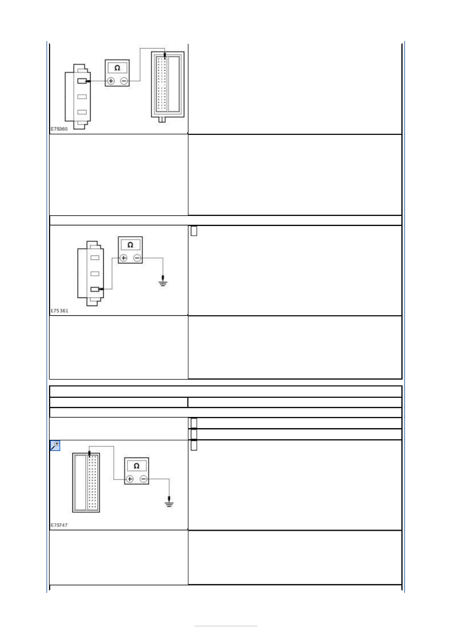
vanity mirror lamp C6LN24 pin 1, circuit CBP17F 
(BN/GN), harness side and the CJB C1BP02-C pin 67, 
circuit CBP17R (BN/GN), harness side. 

Is the resistance less than 1 ohm? 
Yes 

GO to Pinpoint Test 

H. 


No 

REPAIR the circuit CBP17F (BN/GN) or circuit CBP17R 
(BN/GN) as necessary. TEST the system for normal 
operation. If the concern persists, INSTALL a new 
passenger side vanity mirror lamp. TEST the system 
for normal operation. 

G7: CHECK CIRCUIT GD138AH (BK/WH) FOR GROUND

Measure the resistance between the passenger side 
vanity mirror lamp C6LN24 pin 3, circuit GD138AH 

(BK/WH), harness side and ground. 

Is the resistance less than 1 ohm? 
Yes 

INSTALL a new passenger side vanity mirror lamp. 
TEST the system for normal operation 

No 

REPAIR the circuit. TEST the system for normal 
operation. 

PINPOINT TEST H : BATTERY SAVER RELAY TEST 

TEST CONDITIONS

DETAILS/RESULTS/ACTIONS

H1: CHECK THE BATTERY SAVER RELAY

Disconnect CJB C1BP02-C. 

Ignition switch in position II. 

Measure the voltage between the CJB C1BP02-C pin 
67, component side and ground. 

Is the voltage greater than 10 volts? 
Yes 

GO to H2

.  

No 

INSTALL a new CJB. TEST the system for normal 
operation. 


H2: CHECK THE BATTERY SAVER RELAY DISCHARGE

Ignition switch in position 0. 

WAIT for 35 minutes. 

Measure the voltage between the CJB C1BP02-C pin 
67, component side and ground. 

Is the voltage 0 volts? 
Yes 

CONNECT the CJB C1BP02-C. TEST the system for 
normal operation. If the concern persists, INSTALL a 
new CJB. TEST the system for normal operation. 

No 

INSTALL a new CJB. TEST the system for normal 
operation. 


Daytime Running Lamps (DRL) - Daytime 
Running Lamps (DRL)

S-MAX/Galaxy 2006.5 (02/2006-)


Print


Description and Operation 

In areas in which daytime running lamps (DRL) are required by law the generic electronic 
module (GEM) switches on the dipped beam headlamps and the side lights whenever the 
ignition is in position "II" or "III". 

The configuration in the GEM can be changed using the Worldwide Diagnosis System 
(WDS). This makes aftermarket configuration of vehicles with DRL possible (e.g. on 
customer request or in response to changes in the law). 

Vehicles with DRL can be combined with autolamps. 

On vehicles with conventional filament bulbs the GEM switches on the dipped beam 
headlamps and the side lights in light switch position "0", whereby the dipped beam 
headlamps are limited via pulse-width-modulation (PWM) to around 11.5V and therefore 
only operate at 90 % of their normal brightness. 

On vehicles with gas discharge headlamps the PWM control is not active - the dipped beam 
headlamps come on with normal intensity. 

Daytime Running Lamps (DRL) - Daytime 
Running Lamps (DRL)

S-MAX/Galaxy 2006.5 (02/2006-)


Print


Diagnosis and Testing 

Refer to Wiring Diagrams Section 417-04, for schematic and connector 
information.  

Operation 

The daytime running lamps (DRL) system is designed to turn the dipped beam headlamps, 
parking lamps and licence plate lamps ON automatically as soon as engine is running. 

The instrument cluster illumination is not switched on in this mode so as to make the driver 
aware that he has not switched on the normal dipped beam. 

To increase the service life of conventional filament bulbs, the bulbs are operated at a 
reduced voltage of 11.5 volts maximum when the daytime running lamps (DRL) are 
switched on; this also reduces the brightness of the lamps. By contrast, xenon headlamps 
are also operated at a reduced voltage in daytime running lamp (DRL) mode, but they 
operate at normal brightness. 

Vehicles with and without daytime running lamps are no longer distinguished from each 
other by their different headlamp connections; instead, they have different software 
configurations in the GEM. 

The daytime running lamps (DRL) are ON under the following conditions: 

Ignition switch in position RUN and  
Headlight switch in position OFF or  
Headlight switch in automatic headlamps position if light conditions are sufficient. 

The daytime running lamps (DRL) are OFF under the following conditions: 

The ignition switch is in any position except RUN or  
Headlight switch in parking light position or  
Headlight switch in dipped beam position or  
Headlight switch in automatic headlamps position and light conditions are not sufficient. 

Inspection and Testing 

NOTE: Before reading out the vehicle-specific data, remake all the separated electrical 
connections in the vehicle, so that communication between the module and WDS is 
ensured. 
NOTE: The generic electronic module (GEM) forms part of the central junction box (CJB). 
NOTE: If the generic electronic module (GEM) is changed, the new one must be 
reinitialized. For this purpose, the vehicle-specific data is read out of the module to be 
replaced using WDS and is transferred to the new module. REFER to:  

Communications Network

 (418-00 Module Communications Network, Diagnosis and 

Testing), 

Generic Electronic Module (GEM)

 (419-10 Multifunction Electronic Modules, Diagnosis and 

Testing). 

1. 1. Verify the customer concern. 

2. 2. Visually inspect for obvious signs of electrical or mechanical damage. 

Visual Inspection Chart 

Electrical

Fuse(s)  


Content   ..  798  799  800  801   ..