Ford Galaxy / Ford S-MAX. Manual - part 798
 

  Index      Ford     Ford Galaxy / Ford S-MAX - service repair manual 2006 year


Search            


Content   ..  796  797  798  799   ..


Ford Galaxy / Ford S-MAX. Manual - part 798


PINPOINT TEST C : THE REAR INTERIOR LAMP IS INOPERATIVE 

TEST CONDITIONS

DETAILS/RESULTS/ACTIONS

C1: CHECK OPERATION OF THE REAR INTERIOR LAMP

Check for operation of the rear interior lamp in both 
the ON and DOOR OPEN positions. 

Is the rear interior lamp inoperative in both positions? 
Yes 

GO to C3

.  

No 

If the rear interior lamp is inoperative in the ON 
position. 

GO to C5

.  

If the rear interior lamp is inoperative in the DOOR 
OPEN position. 

GO to C2

.  

C2: CHECK CIRCUIT CLN27F (WH/BN) AND CIRCUIT CLN27B (WH/BN) FOR OPEN 
CIRCUIT

Disconnect Rear Interior Lamp C9LN14-D. 

Disconnect CJB C1BP02-H. 

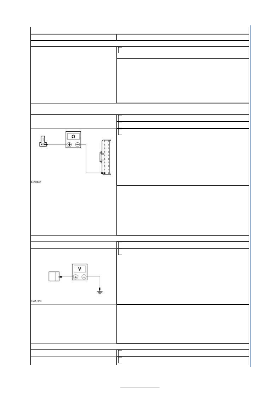
Measure the resistance between the rear interior 
lamp C9LN14-D pin 1, circuit CLN27F (WH/BN), 

harness side and the CJB C1BP02-H pin 20, circuit 
CLN27B (WH/BN), harness side . 

Is the resistance less than 1 ohm? 
Yes 

INSTALL a new rear interior lamp. TEST the system 
for normal operation. 

No 

REPAIR the circuit(s) as necessary. TEST the system 
for normal operation. If the concern persists, 
INSTALL a new CJB. TEST the system for normal 
operation. 

C3: CHECK CIRCUIT CBP17C (BN/GN) FOR VOLTAGE

Disconnect Rear Interior Lamp C9LN14-C. 

Measure the voltage between the rear interior lamp 
C9LN14-C pin 1, circuit CBP17C (BN/GN), harness 

side and ground. 

Is the voltage greater than 10 volts? 
Yes 

INSTALL a new rear interior lamp. TEST the system 
for normal operation. If the concern persists, GO to 
Pinpoint Test 

H. 


No 

GO to C4

.  

C4: CHECK REAR INTERIOR LAMP POWER CIRCUIT FOR OPEN CIRCUIT

Disconnect CJB C1BP02-C. 

Measure the resistance between the rear interior 


lamp C9LN14-C pin 1, circuit CBP17C (BN/GN), 
harness side and the CJB C1BP02-C pin 67, circuit 
CBP17R (BN/GN), harness side. 

Is the resistance less than 1 ohm? 
Yes 

GO to Pinpoint Test 

H. 


No 

REPAIR circuit CBP17C (BN/GN) or circuit CBP17R 
(BN/GN) as necessary . TEST the system for normal 
operation. 

C5: CHECK CIRCUIT GD138M (BK/WH) FOR GROUND

Disconnect the battery ground cable.  
REFER to: 

Battery Disconnect and Connect

 (414-01 

Battery, Mounting and Cables, General Procedures). 

Disconnect Rear Interior Lamp C9LN14-D. 

Measure the resistance between the rear interior 
lamp C9LN14-D pin 2, circuit GD138M (BK/WH), 

harness side and ground. 

Is the resistance less than 1 ohm? 
Yes 

INSTALL a new rear interior lamp. TEST the system 
for normal operation. 

No 

REPAIR the circuit. TEST the system for normal 
operation. 

PINPOINT TEST D : THE LUGGAGE COMPARTMENT LAMP IS INOPERATIVE 

TEST CONDITIONS

DETAILS/RESULTS/ACTIONS

D1: CHECK CIRCUIT CBP17B (BN/GN) FOR VOLTAGE

Ignition switch in position 0. 

Disconnect Luggage Compartment Lamp C4LN13-B. 

Measure the voltage between the luggage 
compartment lamp C4LN13-B pin 1, circuit CBP17B 

(BN/GN), harness side and ground. 

Is the voltage greater than 10 volts? 
Yes 

GO to D3

.  

No 


GO to D2

.  

D2: CHECK LUGGAGE COMPARTMENT LAMP POWER CIRCUIT FOR OPEN CIRCUIT

Disconnect CJB C1BP02-B. 

Measure the resistance between the luggage 
compartment lamp C4LN13-B pin 1, circuit CBP17B 

(BN/GN), harness side and the CJB C1BP02-B pin 56, 
circuit A_CBP17A (BN/GN), harness side. 

Is the resistance less than 1 ohm? 
Yes 

GO to Pinpoint Test 

H. 


No 

REPAIR circuit CBP17B (BN/GN) or circuit A_CBP17A 
(BN/GN) as necessary . TEST the system for normal 
operation. 

D3: CHECK THE SWITCHED SIGNAL TO THE LUGGAGE COMPARTMENT LAMP

Disconnect Liftgate Latch Motor C4PL17. 

Measure the resistance between the luggage 
compartment lamp C4LN13-B pin 2, circuit CLN13B 

(WH/BU), harness side and the liftgate latch motor 
C4PL17 pin 4, circuit CLN13C (WH/BU), harness side. 

Is the resistance less than 1 ohm? 
Yes 

INSTALL a new luggage compartment lamp. TEST the 
system for normal operation. If the concern persists, 

GO to D4

.  

No 

REPAIR circuit CLN13B (WH/BU) or circuit CLN13C 
(WH/BU) as necessary . TEST the system for normal 
operation. 

D4: CHECK THE LIFTGATE LATCH MOTOR FOR GROUND

Measure the resistance between the liftgate latch 
motor C4PL17 pin 2, circuit GD150Y (BK/WH), 

harness side and ground. 

Is the resistance less than 5 ohms? 
Yes 

INSTALL a new liftgate latch motor.  
REFER to: 

Liftgate Latch

 (501-14 Handles, Locks, 

Latches and Entry Systems, Removal and 
Installation). 
TEST the system for normal operation. 


No 

REPAIR the circuit GD150Y (BK/WH). TEST the 
system for normal operation. 

PINPOINT TEST E : THE GLOVE COMPARTMENT LAMP IS INOPERATIVE 

TEST CONDITIONS

DETAILS/RESULTS/ACTIONS

E1: CHECK CIRCUIT CBP17N (BN/GN) FOR VOLTAGE

Disconnect Glove Compartment Lamp C2LN15. 

Measure the voltage between the glove compartment 
lamp C2LN15 pin 1, circuit CBP17N (BN/GN), 

harness side and ground. 

Is the voltage greater than 10 volts? 
Yes 

GO to E3

.  

No 

GO to E2

.  

E2: CHECK THE GLOVE COMPARTMENT LAMP POWER CIRCUIT FOR OPEN CIRCUIT

Disconnect CJB C1BP02-C. 

Measure the resistance between the glove 
compartment lamp C2LN15 pin 1, circuit CBP17N 

(BN/GN), harness side and the CJB C1BP02-C pin 67, 
circuit CBP17R (BN/GN), harness side. 

Is the resistance less than 1 ohm? 
Yes 

GO to Pinpoint Test 

H. 


No 

REPAIR circuit CLN15 pin 1, circuit CBP17N (BN/GN) 
or circuit CBP17R (BN/GN) as necessary. TEST the 
system for normal operation. 

E3: CHECK CIRCUIT GD138AU (BK/WH) FOR GROUND

Measure the resistance between the glove 
compartment lamp C2LN15 pin 2, circuit GD138AU 

(BK/WH), harness side and ground. 

Is the resistance less than 1 ohm? 
Yes 

INSTALL a new glove compartment lamp. TEST the 
system for normal operation. 

No 


Content   ..  796  797  798  799   ..