Ford Galaxy / Ford S-MAX. Manual - part 790
 

  Index      Ford     Ford Galaxy / Ford S-MAX - service repair manual 2006 year


Search            


Content   ..  788  789  790  791   ..


Ford Galaxy / Ford S-MAX. Manual - part 790


SIGNAL SWITCHED ON

Ignition switch in position II. 

SWITCH ON the left-hand turn signal. 

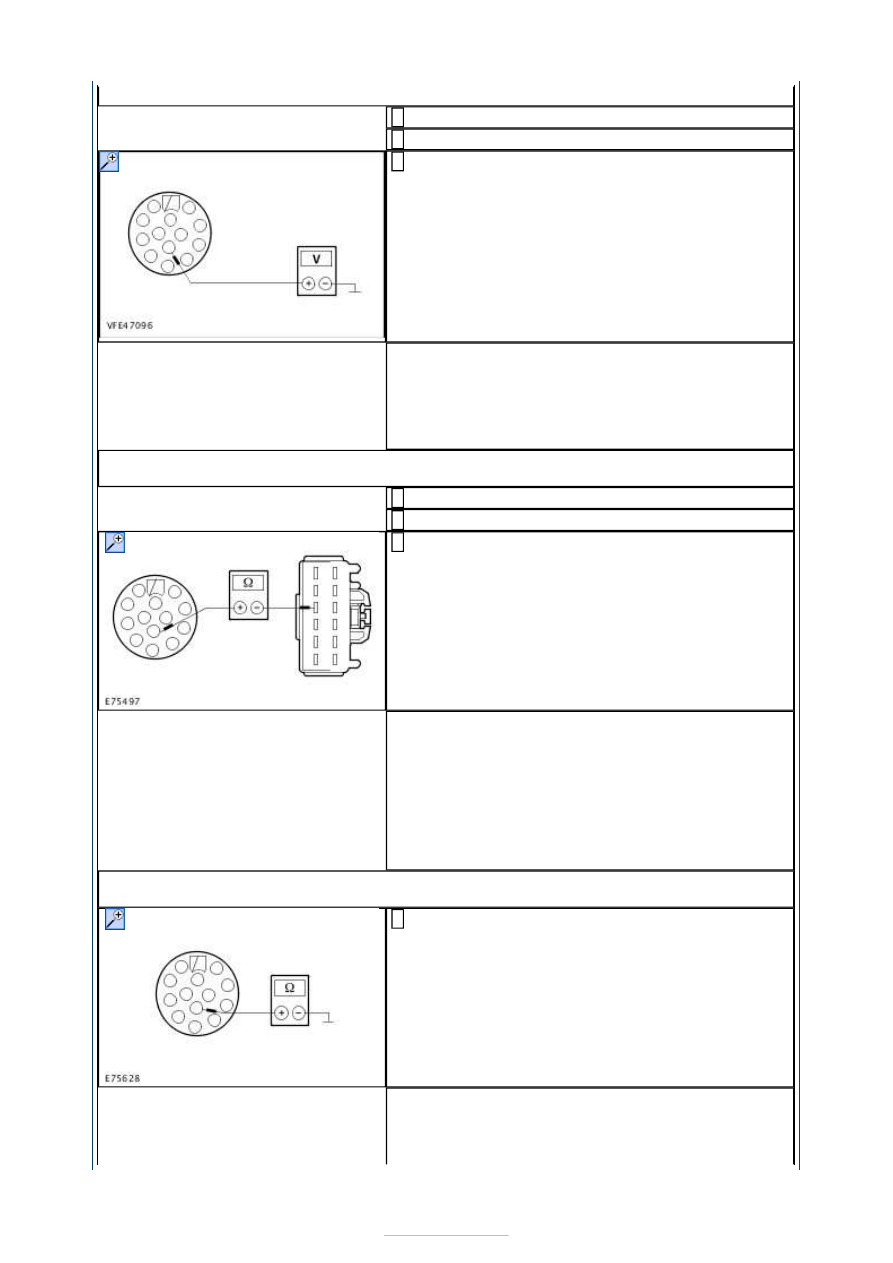
Measure the voltage between the trailer socket, 
connector C4AT23-D, pin 1, circuit CAT06A (BU) 

and ground. 

Does the voltage alternate between 0 V and battery 
voltage? 
Yes 

Continue fault finding on the trailer. 

No 

GO to B3

.  

B3: CHECK CIRCUIT CAT06A (BU) BETWEEN THE TRAILER MODULE (TRM) AND THE 
TRAILER SOCKET FOR OPEN CIRCUIT

Ignition switch in position 0. 

Disconnect TRM from connector C4AT23-A. 

Measure the resistance between the TRM, 
connector C4AT23-A, pin 10, circuit CAT06A (BU), 

wiring harness side and the trailer socket, 
connector C4AT23-D, pin 1, circuit CAT06A (BU), 
wiring harness side. 

Is a resistance of less than 2 Ohms registered? 
Yes 

GO to B4

.  

No 

LOCATE and RECTIFY the break in the circuit 
between the TRM and the trailer socket with the aid 
of the Wiring Diagrams. CHECK system operates 
correctly If necessary RENEW the trailer socket. 
CHECK system operates correctly 

B4: CHECK CIRCUIT CAT06A (BU) BETWEEN THE TRAILER MODULE (TRM) AND THE 
TRAILER SOCKET FOR SHORT TO GROUND

Measure the resistance between the trailer socket, 
connector C4AT23-D, pin 1, circuit CAT06A (BU), 

wiring harness side and ground. 

Is a resistance of more than 10,000 Ohm measured? 
Yes 

INSTALL A NEW TRM. CHECK system operates 
correctly 


No 

LOCATE and RECTIFY the short to ground in the 
circuit between the TRM and the trailer socket with 
the aid of the wiring diagrams. CHECK system 
operates correctly If necessary RENEW the trailer 
socket. CHECK system operates correctly 

B5: CHECK THE VOLTAGE AT THE TRAILER SOCKET WITH THE RIGHT-HAND TURN 
SIGNAL SWITCHED ON

Ignition switch in position II. 

SWITCH ON the right-hand turn signal. 

Measure the voltage between the trailer socket, 
connector C4AT23-D, pin 4, circuit CAT09A (BU) 

and ground. 

Does the voltage alternate between 0 V and battery 
voltage? 
Yes 

Continue fault finding on the trailer. 

No 

GO to B6

.  

B6: CHECK CIRCUIT CAT09A (BU/RD) BETWEEN THE TRAILER MODULE (TRM) AND 
THE TRAILER SOCKET FOR OPEN CIRCUIT

Ignition switch in position 0. 

Disconnect TRM from connector C4AT23-A. 

Measure the resistance between the TRM, 
connector C4AT23-A, pin 1, circuit CAT09A 

(BU/RD), wiring harness side and the trailer socket, 
connector C4AT23-D, pin 4, circuit CAT09A 
(BU/RD), wiring harness side. 

Is a resistance of less than 2 Ohms registered? 
Yes 

GO to B7

.  

No 

LOCATE and RECTIFY the break in the circuit 
between the TRM and the trailer socket with the aid 
of the Wiring Diagrams. CHECK system operates 
correctly If necessary RENEW the trailer socket. 
CHECK system operates correctly 

B7: CHECK CIRCUIT CAT09A (BU/RD) BETWEEN THE TRAILER MODULE (TRM) AND 
THE TRAILER SOCKET FOR SHORT TO GROUND

Measure the resistance between the trailer socket, 
connector C4AT23-D, pin 4, circuit CAT09A 

(BU/RD), wiring harness side and ground. 


Is a resistance of more than 10,000 Ohm measured? 
Yes 

INSTALL A NEW TRM. CHECK system operates 
correctly 

No 

LOCATE and RECTIFY the short to ground in the 
circuit between the TRM and the trailer socket with 
the aid of the wiring diagrams. CHECK system 
operates correctly If necessary RENEW the trailer 
socket. CHECK system operates correctly 

B8: CHECK THE VOLTAGE AT THE TRAILER SOCKET WITH THE SIDE LIGHTS 
SWITCHED ON

Switch on side light. 

Measure the voltage between the trailer socket, 
connector C4AT23-D, pin 7, circuit CAT11A (OG) 

and ground. 

Does the meter display battery voltage? 
Yes 

Continue fault finding on the trailer. 

No 

LOCATE and RECTIFY the break in the circuit 
between the TRM and the trailer socket with the aid 
of the Wiring Diagrams. CHECK system operates 
correctly If necessary RENEW the trailer socket. 
CHECK system operates correctly 

B9: CHECK THE VOLTAGE AT THE TRAILER SOCKET WITH THE SIDE LIGHTS 
SWITCHED ON

Switch on side light. 

Measure the voltage between the trailer socket, 
connector C4AT23-D, pin 5, circuit CAT11B (OG) 

and ground. 

Does the meter display battery voltage? 
Yes 

Continue fault finding on the trailer. 


No 

LOCATE and RECTIFY the break in the circuit 
between the TRM and the trailer socket with the aid 
of the Wiring Diagrams. CHECK system operates 
correctly If necessary RENEW the trailer socket. 
CHECK system operates correctly 

PINPOINT TEST C : THE TRAILER LAMPS ARE ON CONTINUOUSLY 

TEST 

CONDITIONS

DETAILS/RESULTS/ACTIONS

C1: DETERMINE THE FAULT CONDITION

NOTE: Ensure that no adapter or trailer is connected to the trailer coupling socket. 

Ignition switch in position II. 

CHECK the stop lamps at the vehicle. 

Are the stoplamps on the vehicle permanently lit? 
Yes 

REFER to: 

Stoplamps

 (417-01 Exterior Lighting, Diagnosis and Testing). 

No 

GO to C2

.  

C2: RULE OUT THE TRAILER MODULE (TRM) AS THE CAUSE OF THE FAULT

Connect a test adapter or trailer to the trailer coupling socket. 

Ignition switch in position 0. 

Disconnect Fuse FA11 (40 A) (RJB) . 

Ignition switch in position II. 

CHECK the trailer lamps. 

Are there any lamps on the trailer which are permanently lit? 
Yes 

- Left-hand trailer turn signal lamp permanently lit: LOCATE and RECTIFY 
the short to battery voltage in circuit CAT06A (BU) between the TRM and 
the trailer socket with the aid of the Wiring Diagrams. CHECK system 
operates correctly If necessary RENEW the trailer socket. CHECK system 
operates correctly 
- Right-hand trailer turn signal lamp permanently lit: LOCATE and RECTIFY 
the short to battery voltage in circuit CAT09A (BU/RD) between the TRM 
and the trailer socket with the aid of the Wiring Diagrams. CHECK system 
operates correctly If necessary RENEW the trailer socket. CHECK system 
operates correctly 
- Trailer stoplamps permanently lit: LOCATE and RECTIFY the short to 
battery voltage in circuit CAT19A (VT) between the TRM and the trailer 
socket with the aid of the Wiring Diagrams. CHECK system operates 
correctly If necessary RENEW the trailer socket. CHECK system operates 
correctly 
- Trailer backup lamp permanently lit: LOCATE and RECTIFY the short to 
battery voltage in circuit CAT03A (VT/OG) between the TRM and the trailer 
socket with the aid of the Wiring Diagrams. CHECK system operates 
correctly If necessary RENEW the trailer socket. CHECK system operates 
correctly 
- Rear trailer fog lamp permanently lit: LOCATE and RECTIFY the short to 
battery voltage in circuit CAT07A (RD/YE) between the TRM and the trailer 
socket with the aid of the Wiring Diagrams. CHECK system operates 
correctly If necessary RENEW the trailer socket. CHECK system operates 
correctly 
- Rear trailer lamps permanently lit: LOCATE and RECTIFY the short to 
battery voltage in the circuits connected to the TRM, connector C4AT23-A, 
pin 12 with the aid of the Wiring Diagrams. CHECK system operates 
correctly If necessary RENEW the trailer socket. CHECK system operates 
correctly 

No 


Content   ..  788  789  790  791   ..