Ford Galaxy / Ford S-MAX. Manual - part 777
 

  Index      Ford     Ford Galaxy / Ford S-MAX - service repair manual 2006 year


Search            


Content   ..  775  776  777  778   ..


Ford Galaxy / Ford S-MAX. Manual - part 777


Pinpoint test 

NOTE: Use a digital multimeter for all electrical measurements. 

Trailer socket 

*

PINPOINT TEST A : THE BACKUP LAMPS ARE INOPERATIVE 

TEST CONDITIONS

DETAILS/RESULTS/ACTIONS

A1: CHECK FUSE F11 (7.5 A) (SJB)

Ignition switch in position 0. 

Disconnect Fuse F11 (7.5 A) (SJB). 

CHECK Fuse F11 (7.5 A) (SJB). 

Is the fuse OK.? 
Yes 

GO to A2

.  

No 

INSTALL A NEW fuse F11 (7.5 A) (SJB). CHECK 
system operates correctly If the fuse blows again, 
LOCATE and RECTIFY short using the Wiring 
Diagrams. CHECK system operates correctly 

A2: CHECK THE VOLTAGE SUPPLY TO FUSE F11 (7.5 A) (SJB) FOR OPEN CIRCUIT

Connect Fuse F11 (7.5 A) (SJB). 

Ignition switch in position II. 

Measure the voltage between fuse F11 (7.5 A) 
(SJB) and ground. 

Does the meter display battery voltage? 
Yes 

GO to A3

.  

No 

LOCATE AND RECTIFY the break in the voltage 
supply of fuse F11 (7.5 A) (SJB) using the Wiring 
Diagrams. CHECK system operates correctly 

A3: RULE OUT THE BACKUP LAMP SWITCH AS A POSSIBLE CAUSE OF THE FAULT

Ignition switch in position 0. 

Disconnect Backup lamp switch from. 

Manual transmission (SIGMA): Connector 
C1ET47B 

Manual transmission (all other variants): 
Connector C1ET47A 

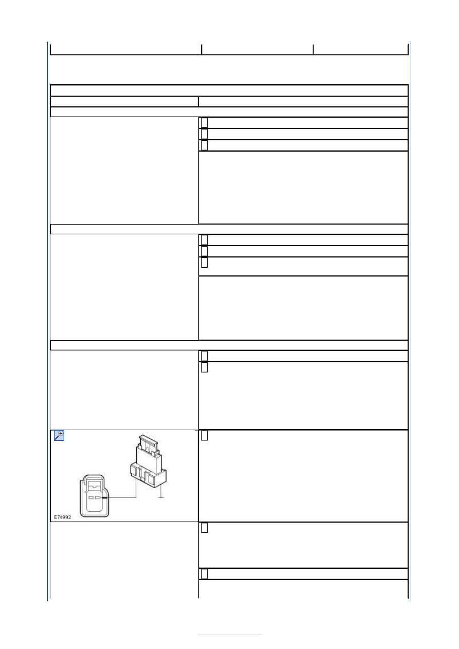
Manual transmission (SIGMA): Connect a fused (5 
A) jumper lead at the backup lamp switch, 

connector C1ET47B, between pin 1, circuit (BU), 
wiring harness side and ground. 

Manual transmission (all other variants): Connect a 
fused jumper lead (5 A) at the backup lamp switch, 

connector C1ET47A, between pin 1, circuit (BU), 
wiring harness side and pin 2, circuit GD120S 
(BK/GN) / GD120B (BK/GN), wiring harness side. 

Ignition switch in position II. 

Are the backup lamps illuminated? 


Yes 

INSTALL A NEW backup lamp switch. CHECK 
system operates correctly 

No 

- Manual transmission (SIGMA): 

GO to A5

.  

- Manual transmission (all other variants):

GO to 

A4

.  

A4: CHECK THE GROUND CONNECTION OF THE BACKUP LAMP SWITCH FOR OPEN 
CIRCUIT

Ignition switch in position 0. 

Measure the resistance between the backup lamp 
switch, connector C1ET47A, pin 2, circuit GD120S 

(BK/GN) / GD120B (BK/GN), wiring harness side 
and ground. 

Is a resistance of less than 2 Ohm registered? 
Yes 

GO to A5

.  

No 

LOCATE and RECTIFY the break in the circuit 
between the backup lamp switch and soldered 
connection SP358 using the Wiring Diagrams. 
CHECK system operates correctly 

A5: CHECK THE CIRCUIT BETWEEN THE SMART JUNCTION BOX AND THE BACKUP 
LAMP SWITCH FOR OPEN CIRCUIT

Ignition switch in position 0. 

Disconnect Smart Junction Box from connector 
C1BP02A. 

Connect Backup lamp switch to. 

Manual transmission (SIGMA): Connector 
C1ET47B 

Manual transmission (all other variants): 
Connector C1ET47A 

ENGAGE the reverse gear. 

Measure the resistance between the Smart 
Junction Box, connector C1BP02A, pin 26, circuit 

CET47B (BU), wiring harness side and ground. 

Is a resistance of less than 2 Ohm registered? 
Yes 

GO to A6

.  

No 

LOCATE and RECTIFY the break in the circuit 
between the Smart Junction Box and the backup 
lamp switch with the aid of the Wiring Diagrams. 
CHECK system operates correctly 

A6: CHECK THE SHARED GROUND OF THE BACKUP LAMPS FOR OPEN CIRCUIT

Disconnect Left-hand rear lamp assembly from 
connector C4LS35. 

Measure the resistance between the left-hand rear 
lamp assembly (tailgate), connector C4LS35, pin 2, 


circuit GD150P (BK/WH), wiring harness side and 
ground. 

Is a resistance of less than 2 Ohm registered? 
Yes 

INSTALL A NEW Smart Junction Box. CHECK 
system operates correctly 

No 

LOCATE and RECTIFY the break in the circuit 
between soldered connection SP534 and ground 
connection G4D149 with the aid of the Wiring 
Diagrams. CHECK system operates correctly 

PINPOINT TEST B : ONE BACKUP LAMP IS INOPERATIVE 

TEST CONDITIONS

DETAILS/RESULTS/ACTIONS

B1: DETERMINE CONDITIONS UNDER WHICH THE FAULT OCCURS

Ignition switch in position II. 

ENGAGE the reverse gear. 

CHECK the backup lamps. 

Is the left-hand backup lamp inoperative? 
Yes 

GO to B2

.  

No 

Right-hand backup lamp inoperative: 

GO to B5

.  

B2: CHECK THE POWER SUPPLY OF THE LEFT-HAND TAILGATE LAMP ASSEMBLY FOR 
OPEN CIRCUIT

Ignition switch in position 0. 

Disconnect Left-hand tailgate lamp assembly from 
connector C4LS35. 

Ignition switch in position II. 

ENGAGE reverse gear. 

Measure the voltage between the left-hand tailgate 
lamp assembly, connector C4LS35, pin 4, circuit 

A_CLS10A (GN/BN), wiring harness side and 
ground. 

Does the meter display battery voltage? 
Yes 

GO to B4

.  

No 

GO to B3

.  

B3: CHECK THE POWER SUPPLY OF THE LEFT-HAND TAILGATE LAMP ASSEMBLY FOR 
OPEN CIRCUIT

Ignition switch in position 0. 


Disconnect Smart Junction Box from connector 
C1BP02B. 

Measure the resistance between the Smart 
Junction Box, connector C1BP02B, pin 73, circuit 

A_CLS10B (GN/BN), wiring harness side and the 
left-hand tailgate lamp assembly, connector 
C4LS35, pin 4, circuit A_CLS10A (GN/BN), wiring 
harness side. 

Is a resistance of less than 2 Ohm registered? 
Yes 

INSTALL A NEW Smart Junction Box. CHECK 
system operates correctly 

No 

LOCATE and RECTIFY the break in the circuit 
between the Smart Junction Box and the tailgate 
lamp assembly with the aid of the Wiring Diagrams. 
CHECK system operates correctly 

B4: CHECK THE GROUND CONNECTION OF THE LEFT-HAND TAILGATE LAMP 
ASSEMBLY FOR OPEN CIRCUIT

Ignition switch in position 0. 

Measure the resistance between the left-hand 
tailgate lamp assembly, connector C4LS35, pin 2, 

circuit GD150P (BK/WH), wiring harness side and 
ground. 

Is a resistance of less than 2 Ohm registered? 
Yes 

INSTALL A NEW tailgate lamp unit. CHECK system 
operates correctly 

No 

LOCATE and RECTIFY the break in the circuit 
between the tailgate lamp unit and soldered 
connection SP534 with the aid of the Wiring 
Diagrams. CHECK system operates correctly 

B5: CHECK THE POWER SUPPLY OF THE RIGHT-HAND TAILGATE LAMP ASSEMBLY FOR 
OPEN CIRCUIT

Ignition switch in position 0. 

Disconnect Right-hand tailgate lamp assembly 
from connector C4LS36. 

Ignition switch in position II. 

ENGAGE the reverse gear. 

Measure the voltage between the right-hand 
tailgate lamp assembly, connector C4LS36, pin 4, 

circuit CLS10A (GN/BN), wiring harness side and 
ground. 

Does the meter display battery voltage? 


Content   ..  775  776  777  778   ..