Ford Galaxy / Ford S-MAX. Manual - part 774
 

  Index      Ford     Ford Galaxy / Ford S-MAX - service repair manual 2006 year


Search            


Content   ..  772  773  774  775   ..


Ford Galaxy / Ford S-MAX. Manual - part 774


Is a resistance of less than 2 Ohm registered? 
Yes 

GO to A9

.  

No 

LOCATE and RECTIFY the break in the circuits 
between the lights control module and soldered 
connection SP581 with the aid of the Wiring 
Diagrams. CHECK system operates correctly 

A9: RULE OUT THE LIGHTS CONTROL MODULE AS A POSSIBLE CAUSE OF THE FAULT

CHECK the lights control module. 

Is the lights control module OK? 
Yes 

GO to A10

.  

No 

INSTALL A NEW lights control module. CHECK 
system operates correctly 

A10: CHECK THE VOLTAGE SUPPLY TO THE SMART JUNCTION BOX FOR OPEN 
CIRCUIT

Disconnect Smart Junction Box from connector 
C1BP02G. 

Ignition switch in position II. 

Measure the voltage between the Smart Junction 
Box, connector C1BP02G, pin 1, circuit SBB17A 

(RD), wiring harness side and ground. 

Does the meter display battery voltage? 
Yes 

GO to A11

.  

No 

LOCATE and RECTIFY the break in the circuits 
between fuse F17 (60 A) (EJB) and the Smart 
Junction Box with the aid of the wiring diagrams. 
CHECK system operates correctly 

A11: CHECK THE VOLTAGE SUPPLY TO THE SMART JUNCTION BOX FOR OPEN 
CIRCUIT

Measure the voltage between the Smart Junction 
Box, connector C1BP02G, pin 2, circuit SBB18A 

(YE), wiring harness side and ground. 


Does the meter display battery voltage? 
Yes 

GO to A12

.  

No 

LOCATE and RECTIFY the break in the circuits 
between fuse F18 (60 A) (EJB) and the Smart 
Junction Box with the aid of the wiring diagrams. 
CHECK system operates correctly 

A12: CHECK THE GROUND CONNECTION TO THE SMART JUNCTION BOX FOR OPEN 
CIRCUIT

Ignition switch in position 0. 

Disconnect Smart Junction Box from connector 
C1BP02A. 

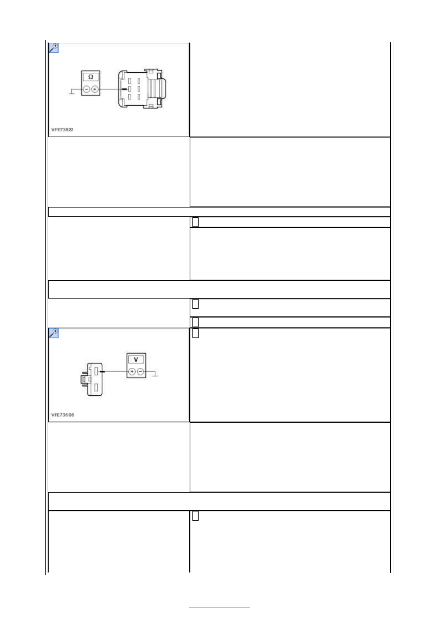
Measure the resistance between the Smart 
Junction Box, connector C1BP02A, pin 54, wiring 

harness side GD123F (BK/GY) and ground. 

Is a resistance of less than 2 Ohm registered? 
Yes 

GO to A13

.  

No 

LOCATE and RECTIFY the break in the circuits 
between the Smart Junction Box and ground with 
the aid of the Wiring Diagrams. CHECK system 
operates correctly 

A13: CHECK THE GROUND CONNECTION TO THE SMART JUNCTION BOX FOR OPEN 
CIRCUIT

Disconnect Smart Junction Box from connector 
C1BP02B. 

Measure the resistance between the lights control 
module, connector C1BP02B, pin 65: 

LHD: circuit GD140J (BK/GN), wiring harness 
side and ground. 

RHD: circuit GD134U (BK/VT), wiring harness 
side and ground. 

Is a resistance of less than 2 Ohm registered? 
Yes 

GO to A14

.  

No 


- LHD: LOCATE AND RECTIFY the break in the 
circuits between the lights control module and 
ground connection G3D138 with the aid of the 
Wiring Diagrams. CHECK system operates correctly 
- RHD: LOCATE AND RECTIFY the break in the 
circuits between the lights control module and 
ground connection G3D133 with the aid of the 
Wiring Diagrams. CHECK system operates correctly 

A14: CHECK THE LIN DATA BUS CONNECTION BETWEEN THE LIGHTS CONTROL 
MODULE AND THE SMART JUNCTION BOX FOR SHORT CIRCUIT TO BATTERY VOLTAGE

Ignition switch in position II. 

Measure the voltage between the lights control 
module, connector C2LF23D, pin 6, circuit VLF25A 

(GN/VT), wiring harness side and ground. 

Does the meter display battery voltage? 
Yes 

GO to A15

.  

No 

LOCATE and RECTIFY the short to battery voltage 
in the circuits between the lights control module 
and the Smart Junction Box with the aid of the 
wiring diagrams. CHECK system operates correctly 

A15: CHECK THE LIN DATA BUS CONNECTION BETWEEN THE LIGHTS CONTROL 
MODULE AND THE SMART JUNCTION BOX FOR SHORT CIRCUIT TO GROUND

Ignition switch in position 0. 

Measure the resistance between the lights control 
module, connector C2LF23D, pin 6, circuit VLF25A 

(GN/VT), wiring harness side and ground. 

Is a resistance of more than 10,000 Ohm measured? 
Yes 

GO to A16

.  

No 

LOCATE and RECTIFY the short to ground in the 
circuits between the lights control module and the 
Smart Junction Box with the aid of the wiring 
diagrams. CHECK system operates correctly 

A16: CHECK THE LIN DATA BUS CONNECTION BETWEEN THE LIGHTS CONTROL 
MODULE AND THE SMART JUNCTION BOX FOR OPEN CIRCUIT

Disconnect Smart Junction Box from connector 
C1BP02C. 

Measure the resistance between the lights control 
module, connector C2LF23D, pin 6, circuit VLF25A 

(GN/VT), wiring harness side and the Smart 
Junction Box, connector C1BP02C, pin 52, circuit 


VLF25A (GN/VT), wiring harness side. 

Is a resistance of less than 2 Ohm registered? 
Yes 

CHECK the Smart Junction Box and INSTALL A NEW 
ONE if required. CHECK system operates correctly 
If the concern persists:  
REFER to: 

Communications Network

 (418-00 

Module Communications Network, Diagnosis and 
Testing). 

No 

LOCATE and RECTIFY the open circuit in the circuits 
between the lights control module and the Smart 
Junction Box with the aid of the wiring diagrams. 

PINPOINT TEST B : INDIVIDUAL OR MULTIPLE FOG LAMPS INOPERATIVE 

TEST CONDITIONS

DETAILS/RESULTS/ACTIONS

B1: DETERMINE CONDITIONS UNDER WHICH THE FAULT OCCURS

Ignition switch in position II. 

SWITCH ON the front and rear fog lamps. 

CHECK fog lamps. 

Are one or more front fog lamps inoperative? 
Yes 

- Left-hand front fog lamp inoperative: 

GO to B4

.  

- Right-hand front fog lamp inoperative: 

GO to B7

.  

- Both front fog lamps inoperative: 

GO to B2

.  

No 

- Left-hand rear fog lamp inoperative: 

GO to B11

.  

- Right-hand rear fog lamp inoperative: 

GO to B14

- Both rear fog lamps inoperative: 

GO to B10

.  

B2: CHECK FUSE F13 (15 A) (SJB)

Ignition switch in position 0. 

Disconnect Fuse F13 (15 A) (SJB). 

CHECK Fuse F13 (15 A) (SJB). 

Is the fuse OK.? 
Yes 

GO to B3

.  

No 

RENEW fuse F13 (15 A) (SJB) and CHECK the 
operation of the system. If the fuse blows again, 
LOCATE and RECTIFY the short to ground using the 
Wiring Diagrams. CHECK system operates correctly 

B3: CHECK THE VOLTAGE SUPPLY TO FUSE F13 (15 A) (SJB) FOR OPEN CIRCUIT

Connect Fuse F13 (15 A) (SJB). 

Ignition switch in position II. 

Measure the voltage between fuse F13 (15 A) 
(SJB) and ground. 

Does meter display battery voltage? 
Yes 


Content   ..  772  773  774  775   ..