Ford Galaxy / Ford S-MAX. Manual - part 705
 

  Index      Ford     Ford Galaxy / Ford S-MAX - service repair manual 2006 year


Search            


Content   ..  703  704  705  706   ..


Ford Galaxy / Ford S-MAX. Manual - part 705


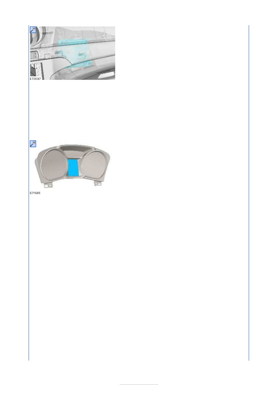
The proximity warning module is located behind the passenger side of the instrument 
panel. 

The proximity warning module receives information from the proximity warning radar unit 
and adjusts the speed of the vehicle using the engine and the brakes to maintain a constant 
time gap to the vehicle in front. The proximity warning module also relays information to 
the instrument cluster to provide the driver with feedback about the system's settings. 
Instrument cluster equipment Level 2 or 3 is required. 

Instrument Cluster 

Information about the adaptive speed control system is displayed to the driver in the 
instrument cluster. Details of the speed and the distance in time are shown. When the 
adaptive speed control system detects that a collision is imminent, the instrument cluster 
will also display an audible and visual warning alerting the driver. 

Service Alignment Procedure 

This procedure is required if:  

A new proximity warning radar unit and, or proximity warning module are 
installed
  
The proximity warning radar unit needed to be removed or is misaligned in its 
position due to another repair operation.
 

Install new components to the vehicle. Make sure that the vehicle is on level ground. 

If the radar assembly was the only new component to be installed, the adaptive speed 
control system will automatically enter 'Service Alignment Mode'. 

The follow indicator will now be flashing, this indicates that the vehicle is in "service 
alignment" and now requires driving. 

The service alignment process measures the path of stationary targets such as streetlights, 
railings, road signs, parked vehicles etc., and uses this data to correct for radar 
misalignment. Alignment will complete more quickly if more suitable targets are seen. The 
following recommendations will help:  

The vehicle speed must be above 30 mph (48 kph).  
Choose a road with plenty of road furniture. Use an inside or outside lane.  
Following vehicles too closely will obscure the stationary targets from the radar, a time 


gap of 2 seconds is recommended.  
A straight road will produce a quicker and better result, although the process will still 
operate on a curved road.  
The time the adaptive speed control module takes to align will vary, depending on the 
route, speed, number of targets, and individual module.  
When the flashing follow indicator light extinguishes, the adaptive speed control system 
is now functional, and a required vehicle speed can now be set by the driver and the 
adaptive speed control system will operate as normal. 

Warning Devices - Warning Devices

S-MAX/Galaxy 2006.5 (02/2006-)


Print


Diagnosis and Testing 

General Equipment 

Inspection and Verification 

NOTE: The safety belt minder can be accidentally activated if items are placed on the 
passenger seat. 

1. 1. Verify the customer concern. 

2. 2. Check the system to make sure that the safety belt minder has not been 

deactivated.  
REFER to: 

Safety Belt Minder Deactivating/Activating

 (413-09 Warning Devices, 

General Procedures). 

3. 3. Visually inspect for obvious signs of mechanical or electrical damage. 

Visual Inspection Chart 

4. 4. If an obvious cause for an observed or reported concern is found, correct the cause 

(if possible) before proceeding to the next step. 

5. 5. If the cause is not visually evident, retrieve the Diagnostic Trouble Codes (DTCs) 

using the 

Ford diagnostic equipment

6. 6. If no DTCs are displayed relating to the symptom, refer to the Symptom Chart. 

Symptom Chart 

Ford Diagnostic Equipment

Mechanical

Electrical

Safety belt buckle 

Wiring harness  
Electrical connector(s)  
Safety belt buckle switch  
Passenger seat mat minder  
Restraints control module (RCM) 

Symptom

Possible Sources

Action

The safety belt indicator does not 
illuminate

Driver safety belt buckle 

switch. 

Passenger safety belt buckle 

switch. 

Passenger seat mat minder. 
Circuit(s). 
RCM. 
Instrument cluster. 

*

*

*
*
*
*

GO to Pinpoint 

Test 

A. 


*

The safety belt indicator is illuminated 
continuously

Driver safety belt buckle 

switch. 

Passenger safety belt buckle 

switch. 

Passenger seat mat minder. 
Circuit(s). 
RCM. 
Instrument cluster. 

*

*

*
*
*
*

GO to Pinpoint 

Test 

B. 


*

PINPOINT TEST A : THE SAFETY BELT INDICATOR DOES NOT ILLUMINATE 

TEST CONDITIONS

DETAILS/RESULTS/ACTIONS

A1: CHECK CIRCUITS CR201A (BU/OG) AND CR203A (GY/VT) FOR SHORT TO 
GROUND 

WARNING: To avoid accidental deployment, the RCM backup power supply must be 

depleted. Wait at least one minute after disconnecting the battery ground cable(s) before 
commencing any repair or adjustment to the supplemental restraint system (SRS), or 
any component(s) adjacent to the SRS sensors. Failure to follow these instructions may 
result in personal injury. 
NOTE: The following tests are to be carried out with the safety belt unbuckled. 

Ignition switch in position 0. 

Disconnect RCM C3R114. 

Measure the resistance between the RCM C3R114 
(driver side) pin 25, circuit CR201A (BU/OG), 

harness side and ground; and between the RCM 
C3R114 (passenger side) pin 30, circuit CR203A 
(GY/VT), harness side and ground. 

Are the resistances less than 5 ohms? 
Yes 

INSTALL a new RCM.  
REFER to: 

Restraints Control Module (RCM)

 (501-

20B Supplemental Restraint System, Removal and 
Installation). 
TEST the system for normal operation. 

No 

Driver side. 

GO to A2

.  

Passenger side. 

GO to A4

.  

A2: CHECK CIRCUIT CR201A (BU/OG) FOR OPEN CIRCUIT

Disconnect Driver Side Underseat Connector 
C3HS03. 

Measure the resistance between the driver side 
underseat connector C3HS03 pin 14, circuit CR201A 

(BU/OG), harness side and the RCM C3R114 pin 25, 
circuit CR201A (BU/OG), harness side. 

Is the resistance less than 5 ohms? 
Yes 

GO to A3

.  

No 

REPAIR circuit CR201A (BU/OG). TEST the system 
for normal operation. 

A3: CHECK CIRCUIT RR155E (GY) FOR GROUND

Measure the resistance between the driver side 
underseat connector C3HS03 pin 13, circuit RR155E 

(GY), harness side and ground. 


Content   ..  703  704  705  706   ..