Ford Galaxy / Ford S-MAX. Manual - part 660
 

  Index      Ford     Ford Galaxy / Ford S-MAX - service repair manual 2006 year


Search            


Content   ..  658  659  660  661   ..


Ford Galaxy / Ford S-MAX. Manual - part 660


Climate Control - Air Conditioning

S-MAX/Galaxy 2006.5 (02/2006-)


Print


Description and Operation 

The air conditioning system is controlled by an thermostatic expansion valve. R134a 
refrigerant is used. 

There are three different variants available: 

Front air conditioning system with manual temperature control  
Front air conditioning system with automatic temperature control (DEATC)  
Front and rear air conditioning system with automatic temperature control (TEATC) 

Depending on the engine variant, two different air conditioning compressors are used: 

Visteon VS16 compressor with variable stroke for 2.0L Duratec-HE (MI4), 1.8L Duratorq-
TDCi (Lynx) and 2.0L Duratorq-TDCi (DW) engines  
Zexel KC88 compressor with variable stroke and electronically regulated control valve for 
2.5L Duratec-ST (VI5) engines 

In order to prevent icing of the evaporator, the vehicles are equipped with a temperature 
sensor on the evaporator. The sensor measures the surface temperature of the cooling fins 
on the evaporator. If the measured temperature drops below a temperature of approx. 2 °C 
then the compressor clutch is deactivated. If the temperature increases above +4 °C the 
compressor is switched back on again. On systems with manual temperature control, the 
sensor signal is sent via the generic electronic module (GEM) and the CAN bus to the 
powertrain control module (PCM), which then switches the compressor clutch on and off. 
On systems with automatic temperature control (DEATC / TEATC) the sensor signal is first 
sent to the air conditioning module and then via the CAN bus to the PCM, which then 
switches the compressor clutch on and off. 

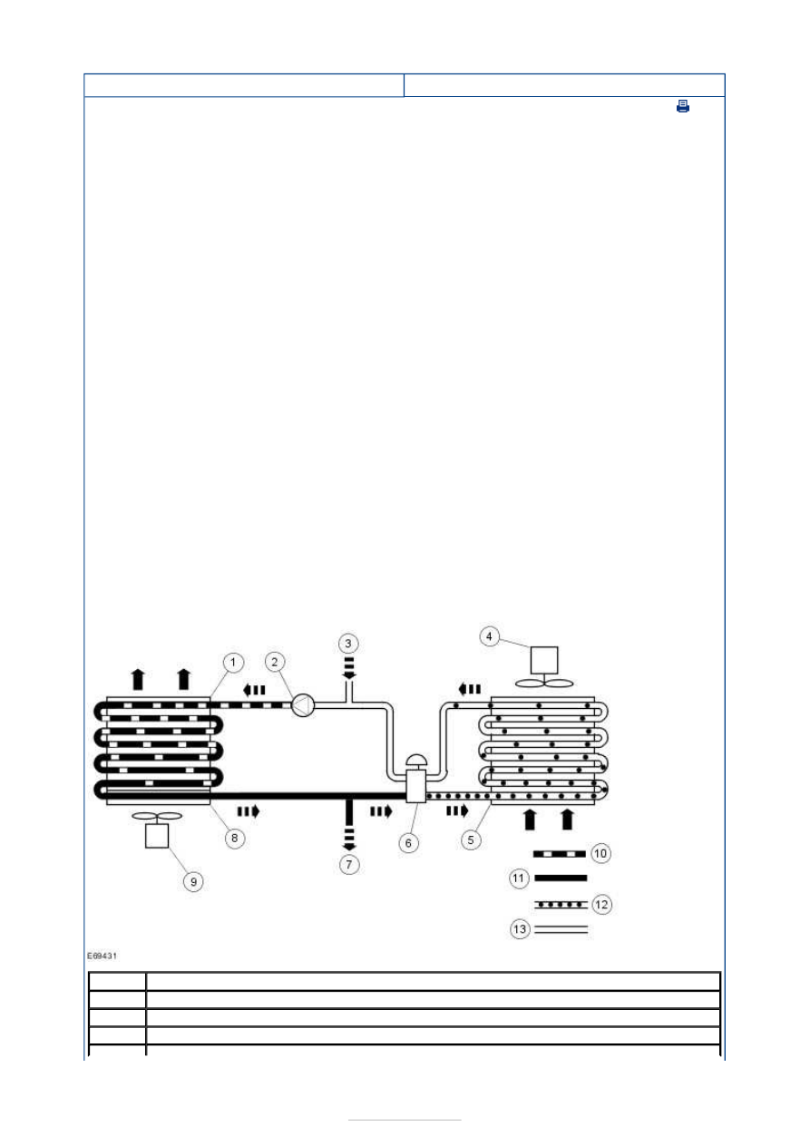
Refrigerant circuit 

Item

Description

1

Condenser

2

A/C compressor

3

Outlet line for the additional evaporator (if equipped)


Operation 

The refrigerant compressor (2) which is driven by the engine sucks in the gaseous 
refrigerant from the evaporator (5) and compresses it. The temperature of the refrigerant 
increases to a value between 70 °C and 110 °C. It is directed under high pressure to the 
condenser (1). At this point heat is drawn from the refrigerant by the air being forced past 
the cooling fins. Because of this heat loss, the refrigerant liquifies and leaves the 
condenser. 

The refrigerant then passes under high pressure to the refrigerant drier (8). This serves as 
a storage medium and filters out any moisture contained in the refrigerant. 

The expansion valve (6) regulates the quantity of refrigerant injected into the evaporator 
(5) as a function of the pressure and temperature in the evaporator. The liquid refrigerant 
is vaporized in the evaporator. As a result, heat is extracted from the air before it enters 
the passenger compartment. The air therefore cools down and the moisture it contained is 
given up at the evaporator core. 

The gaseous flow of refrigerant which comes out from the evaporator at low pressure 
enters the expansion valve at the upper opening, from where it is sucked in by the 
refrigerant compressor. 

The A/C pressure convertor sensor sends an analog signal to the PCM. After evaluating the 
different input signals, the PCM sends a control signal to the A/C clutch relay, which 
engages and disengages the compressor clutch. The PCM input signals come from the 
blower motor switch via the evaporator temperature sensor (vehicles with manual 
temperature control), via the A/C module (vehicles with automatic temperature control), 
the A/C pressure convertor sensor and the PCM. 

Overview of the air conditioning system 

4

Blower motor

5

Evaporator

6

Expansion valve

7

Inlet line for the additional evaporator (if equipped)

8

Refrigerant drier

9

Cooling fan

10

High pressure (gaseous and hot)

11

High - pressure (liquid and warm)

12

Low - pressure (liquid and cool)

13

Low-pressure (gaseous and cool)


Description 

Refrigerant drier 

Condenser 

A/C compressor 

High pressure charging connection 

Refrigerant lines for the additional air conditioning system (if 
equipped) 

A/C pressure convertor sensor 

Low pressure charging connection 

Expansion valve 

Evaporator 

Service evaporator 


Description 

Evaporator 

A/C lines 

Retaining bolt 

The evaporator is located on the right-hand side of the climate control housing (LHD and 
RHD). It can be removed and installed with the climate control housing still installed in the 
vehicle, although the heat exchanger does need to be removed first. The refrigerant lines of 
the production evaporator must be sawn through during removal. An evaporator with 

Item

1

2

3

4

5

6

7

8

9

Item

1

2

3


Part Number

-

-

-

-

-

-

-

-

-


Part Number

-

-

-

separate refrigerant lines is installed in service. 

Electronic refrigerant compressor control valve 

On vehicles with a 2.5L Duratec-ST (VI5) engine a refrigerant compressor with electronic 
control valve is used. The control valve regulates the delivery rate of the refrigerant 
compressor according to the request received from the A/C module. 


Content   ..  658  659  660  661   ..