Ford Galaxy / Ford S-MAX. Manual - part 642
 

  Index      Ford     Ford Galaxy / Ford S-MAX - service repair manual 2006 year


Search            


Content   ..  640  641  642  643   ..


Ford Galaxy / Ford S-MAX. Manual - part 642


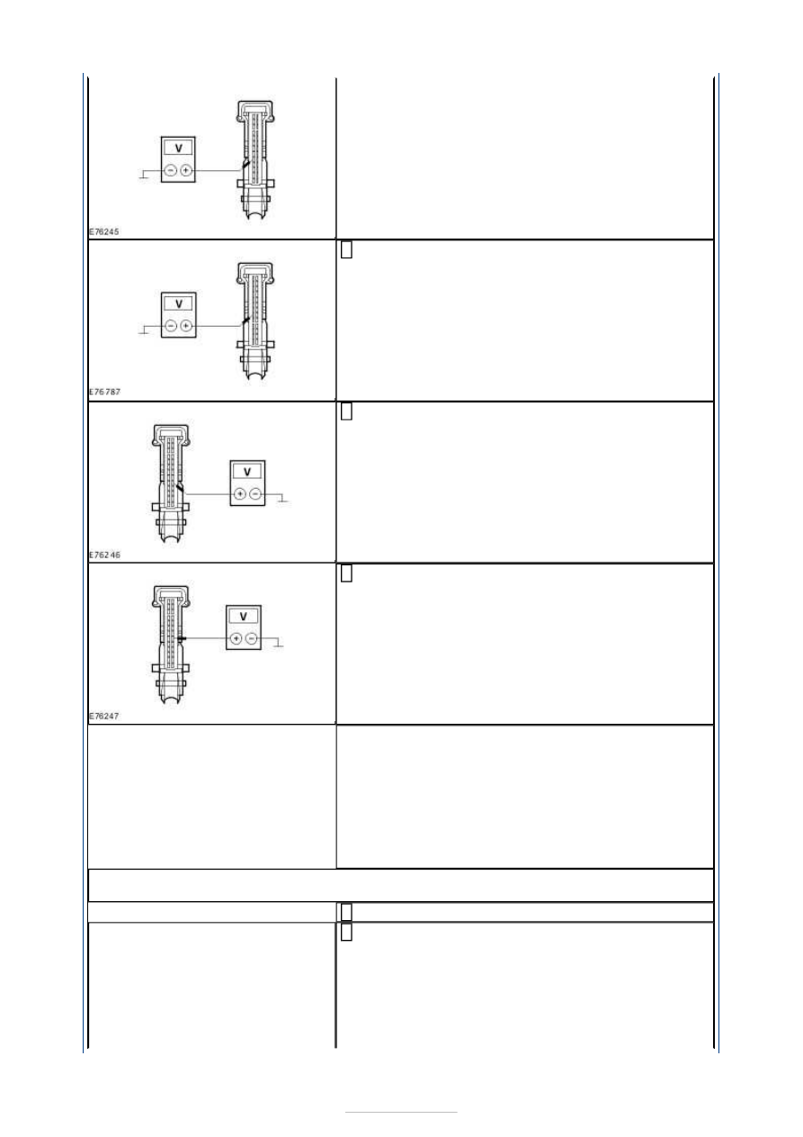
Measure the voltage between the EATC module, 
connector C2H101-A, pin 6, circuit CH203A (GN/BN), 

wiring harness side and ground. 

Measure the voltage between the EATC module, 
connector C2H101-A, pin 18, circuit CH204A 

(GY/OG), wiring harness side and ground. 

Measure the voltage between the EATC module, 
connector C2H101-A, pin 19, circuit CH205A 

(BN/WH), wiring harness side and ground. 

Is a voltage measured during one or more 
measurements? 
Yes 

LOCATE and REPAIR the short to voltage in the 
relevant circuit(s) between the air distribution flap 
actuator and the EATC module using the Wiring 
Diagrams. CHECK the operation of the system. 

No 

GO to G5

.  

G5: CHECK THE CIRCUITS BETWEEN THE AIR DISTRIBUTION FLAP ACTUATOR AND 
THE EATC MODULE FOR SHORT TO GROUND

Ignition switch in position 0. 

Measure the resistance between the EATC module, 
connector C2H101-A, pin 5, circuit CH202A (BU/GN), 

wiring harness side and ground. 


Measure the resistance between the EATC module, 
connector C2H101-A, pin 6, circuit CH203A (GN/BN), 

wiring harness side and ground. 

Measure the resistance between the EATC module, 
connector C2H101-A, pin 18, circuit CH204A 

(GY/OG), wiring harness side and ground. 

Measure the resistance between the EATC module, 
connector C2H101-A, pin 19, circuit CH205A 

(BN/WH), wiring harness side and ground. 

Is a resistance of more than 10,000 Ohms measured in 
all of the measurements? 
Yes 

GO to G6

.  

No 

LOCATE and REPAIR the short to ground in the 
relevant circuit(s) between the air distribution flap 
actuator and the EATC module using the Wiring 
Diagrams. CHECK the operation of the system. 

G6: CHECK THE CIRCUITS BETWEEN THE AIR DISTRIBUTION FLAP ACTUATOR AND 
THE EATC MODULE FOR SHORT CIRCUIT

Measure the resistance between the EATC module, 
connector C2H101-A, pin 5, circuit CH202A (BU/GN), 

wiring harness side and the EATC module, connector 
C2H101-A, pin 26, circuit CH201A (YE/RD), wiring 
harness side. 


Measure the resistance between the EATC module, 
connector C2H101-A, pin 5, circuit CH202A (BU/GN), 

wiring harness side and the EATC module, connector 
C2H101-A, pin 6, circuit CH203A (GN/BN), wiring 
harness side. 

Measure the resistance between the EATC module, 
connector C2H101-A, pin 5, circuit CH202A (BU/GN), 

wiring harness side and the EATC module, connector 
C2H101-A, pin 18, circuit CH204A (GY/OG), wiring 
harness side. 

Measure the resistance between the EATC module, 
connector C2H101-A, pin 5, circuit CH202A (BU/GN), 

wiring harness side and the EATC module, connector 
C1MC40, pin 19, circuit CH205A (BN/WH), wiring 
harness side. 

Measure the resistance between the EATC module, 
connector C2H101-A, pin 26, circuit CH201A 

(YE/RD), wiring harness side and the EATC module, 
connector C2H101-A, pin 6, circuit CH203A (GN/BN), 
wiring harness side. 

Measure the resistance between the EATC module, 
connector C2H101-A, pin 26, circuit CH201A 

(YE/RD), wiring harness side and the EATC module, 
connector C2H101-A, pin 18, circuit CH204A 
(GY/OG), wiring harness side. 


Measure the resistance between the EATC module, 
connector C2H101-A, pin 26, circuit CH201A 

(YE/RD), wiring harness side and the EATC module, 
connector C2H101-A, pin 19, circuit CH205A 
(BN/WH), wiring harness side. 

Measure the resistance between the EATC module, 
connector C2H101-A, pin 6, circuit CH203A (GN/BN), 

wiring harness side and the EATC module, connector 
C2H101-A, pin 18, circuit CH204A (GY/OG), wiring 
harness side. 

Measure the resistance between the EATC module, 
connector C2H101-A, pin 6, circuit CH203A (GN/BN), 

wiring harness side and the EATC module, connector 
C2H101-A, pin 19, circuit CH205A (BN/WH), wiring 
harness side. 

Measure the resistance between the EATC module, 
connector C2H101-A, pin 18, circuit CH204A 

(GY/OG), wiring harness side and the EATC module, 
connector C2H101-A, pin 19, circuit CH205A 
(BN/WH), wiring harness side. 

10 

Is a resistance of more than 10,000 Ohms measured in 
all of the measurements? 
Yes 

RENEW the air distribution flap actuator. CHECK the 
operation of the system. 

No 

LOCATE and REPAIR the short between the relevant 
circuits between the air distribution flap actuator and 
the EATC module using the Wiring Diagrams. CHECK 
the operation of the system. 


Content   ..  640  641  642  643   ..