Ford Galaxy / Ford S-MAX. Manual - part 640
 

  Index      Ford     Ford Galaxy / Ford S-MAX - service repair manual 2006 year


Search            


Content   ..  638  639  640  641   ..


Ford Galaxy / Ford S-MAX. Manual - part 640


circuit VH442B (GN/BN), wiring harness side and 
the PCM, connector C1E108-B, pin 31, circuit 
VH442B (GN/BN), wiring harness side. 

Is a resistance of less than 2 Ohms registered? 
Yes 

CHECK the PCM and RENEW if necessary. CHECK 
the operation of the system. 

No 

LOCATE and REPAIR the break in circuit VH442B 
(GN/BN) between the refrigerant pressure 
transducer and the PCM using the Wiring Diagrams. 
CHECK the operation of the system. 

E49: CHECK THE CIRCUIT BETWEEN THE REFRIGERANT PRESSURE TRANSDUCER AND 
THE PCM FOR OPEN CIRCUIT - VEHICLES WITH A 2.5L ENGINE

Ignition switch in position 0. 

Disconnect Connector C1E108-B from the PCM. 

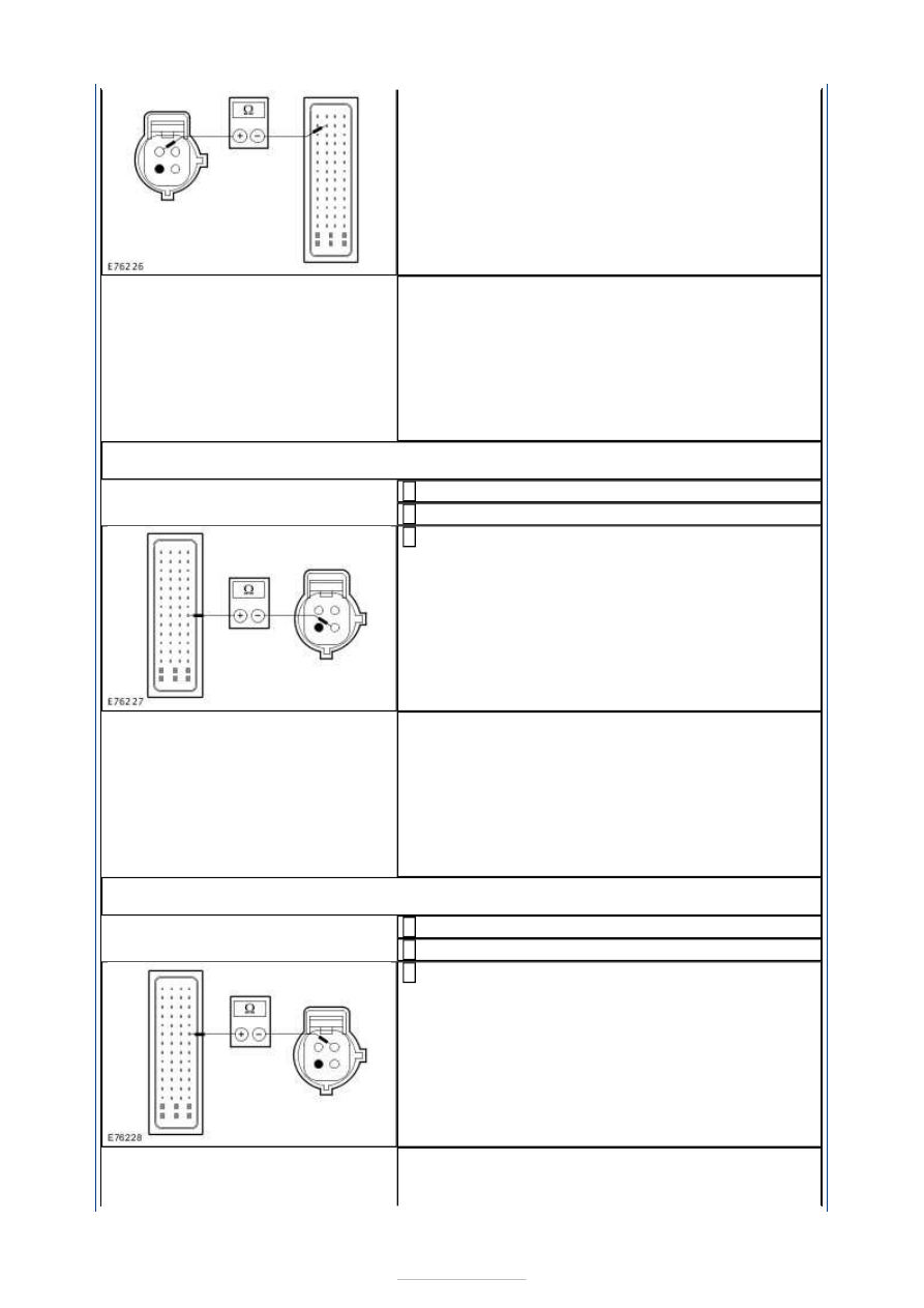
Measure the resistance between the refrigerant 
pressure transducer, connector C1H433, pin 3, 

circuit LH108B (GY/BN), wiring harness side and 
the PCM, connector C1E108-B, pin 51, circuit 
LH108B (GY/BN), wiring harness side. 

Is a resistance of less than 2 Ohms registered? 
Yes 

CHECK the PCM and RENEW if necessary. CHECK 
the operation of the system. 

No 

LOCATE and REPAIR the break in circuit LH108B 
(GY/BN) between the refrigerant pressure 
transducer and the PCM using the Wiring Diagrams. 
CHECK the operation of the system. 

E50: CHECK THE CIRCUIT BETWEEN THE REFRIGERANT PRESSURE TRANSDUCER AND 
THE PCM FOR OPEN CIRCUIT - VEHICLES WITH A 2.5L ENGINE

Ignition switch in position 0. 

Disconnect Connector C1E108-B from the PCM. 

Measure the resistance between the refrigerant 
pressure transducer, connector C1H433, pin 1, 

circuit RH108F (BN), wiring harness side and the 
PCM, connector C1E108-B, pin 53, circuit RH108F 
(BN), wiring harness side. 

Is a resistance of less than 2 Ohms registered? 
Yes 

CHECK the PCM and RENEW if necessary. CHECK 


the operation of the system. 

No 

LOCATE and REPAIR the break in circuit RH108F 
(BN) between the refrigerant pressure transducer 
and the PCM using the Wiring Diagrams. CHECK the 
operation of the system. 

E51: CHECK THE VOLTAGE AT THE AMBIENT AIR TEMPERATURE SENSOR

Ignition switch in position 0. 

Disconnect Connector C1H407 from the ambient air 
temperature sensor. 

Ignition switch in position II. 

Measure the voltage at the ambient air 
temperature sensor, connector C1H407, pin 1, 

circuit VH407A (YE/GN), wiring harness side and 
ground. 

Is a voltage of approx. 5 volts measured? 
Yes 

GO to E52

.  

No 

- Vehicles with a 2.0L diesel engine:

GO to E56

.  

- Vehicles with a 1.8L diesel engine:

GO to E57

.  

- Vehicles with a 2.0L engine:

GO to E58

.  

- Vehicles with a 2.5L engine

GO to E59

.  

E52: CHECK THE GROUND CONNECTION OF THE AMBIENT AIR TEMPERATURE 
SENSOR

Ignition switch in position 0. 

Measure the resistance between the ambient air 
temperature sensor, connector C1H407, pin 2, 

circuit RH107A (GN/BU), wiring harness side and 
ground. 

Is a resistance of less than 2 Ohms registered? 
Yes 

RENEW the ambient air temperature sensor. CHECK 
the operation of the system. 

No 

- Vehicles with a 2.0L engine:LOCATE and RECTIFY 
the break in the circuit between the ambient air 
temperature sensor and ground connection 
G1D108-D with the aid of the Wiring Diagrams. 
CHECK the operation of the system. 
- Vehicles with a 2.0L diesel engine:

GO to E53

.  

- Vehicles with a 1.8L diesel engine:

GO to E54

.  

- Vehicles with a 2.5L engine

GO to E55

.  

E53: CHECK THE CIRCUIT BETWEEN THE AMBIENT AIR TEMPERATURE SENSOR AND 
THE PCM FOR OPEN CIRCUIT - VEHICLES WITH A 2.0L DIESEL ENGINE

Disconnect Connector C1E108-C from the PCM. 


Measure the resistance between the ambient air 
temperature sensor, connector C1H407, pin 2, 

circuit RH107A (GN/BU), wiring harness side and 
the PCM, connector C1E108-C, pin J4, circuit 
RH107B (GN/BU), wiring harness side. 

Is a resistance of less than 2 Ohms registered? 
Yes 

CHECK the PCM and RENEW it as necessary. CHECK 
the operation of the system. 

No 

LOCATE and RECTIFY the break in the circuit 
between the ambient air temperature sensor and 
the PCM with the aid of the Wiring Diagrams. 
CHECK the operation of the system. 

E54: CHECK THE CIRCUIT BETWEEN THE AMBIENT AIR TEMPERATURE SENSOR AND 
THE PCM FOR OPEN CIRCUIT - VEHICLES WITH A 1.8L DIESEL ENGINE

Disconnect Connector C1E108-J from the PCM. 

Measure the resistance between the ambient air 
temperature sensor, connector C1H407, pin 2, 

circuit RH107A (GN/BU), wiring harness side and 
the PCM, connector C1E108-J, pin J4, circuit 
RH107B (GN/BU), wiring harness side. 

Is a resistance of less than 2 Ohms registered? 
Yes 

CHECK the PCM and RENEW it as necessary. CHECK 
the operation of the system. 

No 

LOCATE and RECTIFY the break in the circuit 
between the ambient air temperature sensor and 
the PCM with the aid of the Wiring Diagrams. 
CHECK the operation of the system. 

E55: CHECK THE CIRCUIT BETWEEN THE AMBIENT AIR TEMPERATURE SENSOR AND 
THE PCM FOR OPEN CIRCUIT - VEHICLES WITH A 2.5L ENGINE

Disconnect Connector C1E108-B from the PCM. 

Measure the resistance between the ambient air 
temperature sensor, connector C1H407, pin 2, 

circuit RH107A (GN/BU), wiring harness side and 
the PCM, connector C1E108-B, pin 34, circuit 
RH107B (GN/BU), wiring harness side. 

Is a resistance of less than 2 Ohms registered? 
Yes 

CHECK the PCM and RENEW it as necessary. CHECK 
the operation of the system. 

No 

LOCATE and RECTIFY the break in the circuit 
between the ambient air temperature sensor and 
the PCM with the aid of the Wiring Diagrams. 
CHECK the operation of the system. 

E56: CHECK THE CIRCUIT BETWEEN THE AMBIENT AIR TEMPERATURE SENSOR AND 


THE PCM FOR OPEN CIRCUIT - VEHICLES WITH A 2.0L DIESEL ENGINE

Disconnect Connector C1E108-C from the PCM. 

Measure the resistance between the ambient air 
temperature sensor, connector C1H407, pin 1, 

circuit VH407A (YE/GN), wiring harness side and 
the PCM, connector C1E108-C, Pin H2, circuit 
VH407B (YE/GN), wiring harness side. 

Is a resistance of less than 2 Ohms registered? 
Yes 

CHECK the PCM and RENEW it as necessary. CHECK 
the operation of the system. 

No 

LOCATE and RECTIFY the break in the circuit 
between the ambient air temperature sensor and 
the PCM with the aid of the Wiring Diagrams. 
CHECK the operation of the system. 

E57: CHECK THE CIRCUIT BETWEEN THE AMBIENT AIR TEMPERATURE SENSOR AND 
THE PCM FOR OPEN CIRCUIT - VEHICLES WITH A 1.8L DIESEL ENGINE

Disconnect Connector C1E108-J from the PCM. 

Measure the resistance between the ambient air 
temperature sensor, connector C1H407, pin 1, 

circuit VH407A (YE/GN), wiring harness side and 
the PCM, connector C1E108-J, Pin H2, circuit 
VH407B (YE/GN), wiring harness side. 

Is a resistance of less than 2 Ohms registered? 
Yes 

CHECK the PCM and RENEW it as necessary. CHECK 
the operation of the system. 

No 

LOCATE and RECTIFY the break in the circuit 
between the ambient air temperature sensor and 
the PCM with the aid of the Wiring Diagrams. 
CHECK the operation of the system. 

E58: CHECK THE CIRCUIT BETWEEN THE AMBIENT AIR TEMPERATURE SENSOR AND 
THE PCM FOR OPEN CIRCUIT - VEHICLES WITH A 2.0L ENGINE

Disconnect Connector C1E104-E from the PCM. 

Measure the resistance between the ambient air 
temperature sensor, connector C1H407, pin 1, 

circuit VH407A (YE/GN), wiring harness side and 
the PCM, connector C1E104-E, Pin H2, circuit 
VH407B (YE/GN), wiring harness side. 

Is a resistance of less than 2 Ohms registered? 
Yes 

CHECK the PCM and RENEW it as necessary. CHECK 
the operation of the system. 

No 

LOCATE and RECTIFY the break in the circuit 
between the ambient air temperature sensor and 
the PCM with the aid of the Wiring Diagrams. 


Content   ..  638  639  640  641   ..