Ford Galaxy / Ford S-MAX. Manual - part 550
 

  Index      Ford     Ford Galaxy / Ford S-MAX - service repair manual 2006 year


Search            


Content   ..  548  549  550  551   ..


Ford Galaxy / Ford S-MAX. Manual - part 550


with two friction surfaces and the synchronizer cone also with two friction surfaces. The 
outer synchronizer cone is virtually unchanged. It is fitted into the synchronizer hub with its 
recesses in such a way that it can only turn by half a tooth in both directions. 

An important aspect for the action of the two friction surfaces is the torque proof 
connection between the gear wheel and the intermediate ring. At the same time, the two 
synchronizer rings are also connected together in a torque proof manner via pawls. The 
synchronizer therefore operates like a multiple wet clutch. 

Power flow 

When a gear is to be selected, the synchronizing sleeve in question located on the relevant 
shaft is moved by its selector fork along the synchronizing hub towards the trailing wheel of 
the desired gear. The synchronizing sleeve and synchronizing hub engage and lock the 
trailing wheel to the hub and the relevant countershaft. 

The power flow is transferred from the clutch to the input shaft. The power flow travels 
from the input shaft to a countershaft via a pair of drives consisting of a gear and a trailing 
wheel. The trailing wheel is locked to the hub by means of the synchronizing unit, which 
allows the power flow to be transferred. The power flow is transferred from the 
countershaft via the final drive pinion to the final drive (ring gear) mounted on the 
differential. 

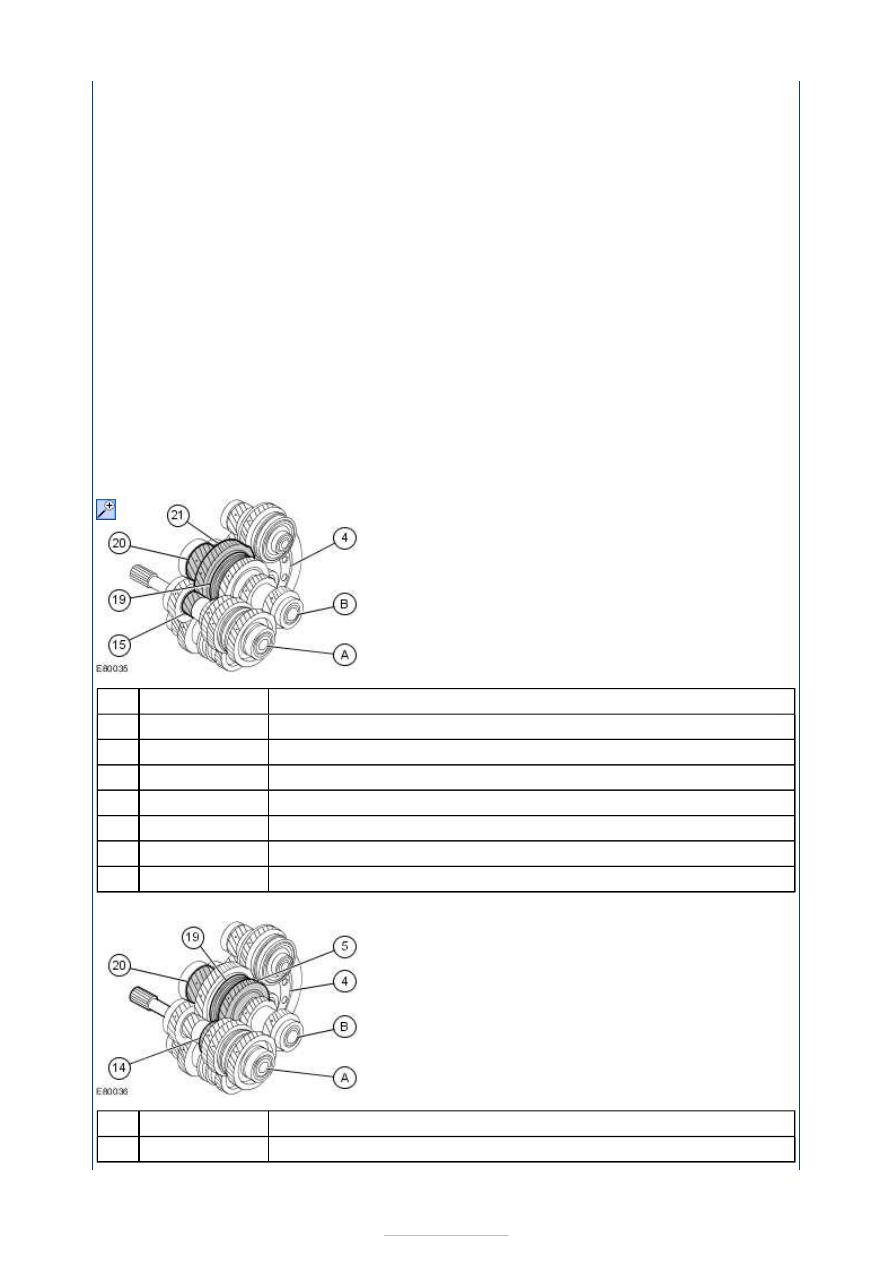
1st gear 


Description 

Input shaft 

1st-2nd and 5th-6th gear output shaft 

Ring gear 

Toothed wheel - 1st gear 

Synchronizer hub - 1st/2nd gear 

Output pinion - 1st-2nd and 5th-6th gear output shaft 

Gear wheel - 1st gear 

2nd gear 


Description 

Input shaft 

Item

A

B

4

15

19

20

21

Item

A


Part Number

-

-

-

-

-

-

-


Part Number

-

-

1st-2nd and 5th-6th gear output shaft 

Ring gear 

Gear wheel - 2nd gear 

Toothed wheel - 2nd gear 

Synchronizer hub - 1st/2nd gear 

Output pinion - 1st-2nd and 5th-6th gear output shaft 

3rd gear 


Description 

Input shaft 

3rd-4th gear output shaft 

Ring gear 

Synchronizer hub - 3rd/4th gear 

Gear wheel - 3rd gear 

Output pinion - 3rd-4th gear output shaft 

Toothed wheel - 3rd gear 

4th gear 


Description 

Input shaft 

3rd-4th gear output shaft 

Ring gear 

Gear wheel - 4th gear 

Synchronizer hub - 3rd/4th gear 

Toothed wheel - 4th gear 

Output pinion - 3rd-4th gear output shaft 

5th gear 

B

4

5

14

19

20

Item

A

C

4

12

16

17

18

Item

A

C

4

10

12

13

17

-

-

-

-

-

-


Part Number

-

-

-

-

-

-

-


Part Number

-

-

-

-

-

-

-


Description 

Input shaft 

1st-2nd and 5th-6th gear output shaft 

Ring gear 

Toothed wheel - 5th gear 

Synchronizer hub - 5th/6th gear 

Gear wheel - 5th gear 

Output pinion - 1st-2nd and 5th-6th gear output shaft 

6th gear 


Description 

Input shaft 

1st-2nd and 5th-6th gear output shaft 

Ring gear 

Toothed wheel - 6th gear 

Gear wheel - 6th gear 

Synchronizer hub - 5th/6th gear 

Output pinion - 1st-2nd and 5th-6th gear output shaft 

Reverse gear 


Description 

Item

A

B

4

6

9

11

20

Item

A

B

4

7

8

9

20

Item


Part Number

-

-

-

-

-

-

-


Part Number

-

-

-

-

-

-

-


Part Number

-

Input shaft 

1st-2nd and 5th-6th gear output shaft 

Reverse gear output shaft 

Output pinion - reverse gear output shaft 

Gear wheel - reverse gear 

Synchronizer hub - reverse gear 

Ring gear 

Toothed wheel - 1st gear 

Gear wheel - 1st gear 

Internal control 


Description 

Shift unit 

5th/6th gear governor 

Carrier plate with gearshift gate 

Switch for reverse gear signal 

Shift guide 

Lower shift finger 

Guide plate 

Upper shift finger 

Spring 

Shift arm with damping weight 

Spring 

Selector lever 

Carrier plate with gearshift gate 

Vent cap 

The gearshift mechanism is secured to the transaxle housing by four bolts and may only be 
replaced as a complete unit in the event of a fault. 

A

B

D

1

2

3

4

15

21

Item

1

2

3

4

5

6

7

8

9

10

11

12

13

14

-

-

-

-

-

-

-

-


Part Number

-

-

-

-

-

-

-

-

-

-

-

-

-

-


Content   ..  548  549  550  551   ..