Ford Galaxy / Ford S-MAX. Manual - part 511
 

  Index      Ford     Ford Galaxy / Ford S-MAX - service repair manual 2006 year


Search            


Content   ..  509  510  511  512   ..


Ford Galaxy / Ford S-MAX. Manual - part 511


Manual Transmission/Transaxle - Vehicles 
With: 5-Speed Manual Transaxle - MTX75 
- Manual Transaxle

S-MAX/Galaxy 2006.5 (02/2006-)


Print


Description and Operation 

Manual Transmission 

MTX-75 means: 

M: Manual  
T: Transmission  
X: Transaxle (front wheel drive)  
75: Distance between input and output shaft in mm.  
Transmission with different axes (input and output shafts)  
The final drive is integrated into the transmission housing. 

5-speed manual transmission for FWD  
1st/2nd gear double synchroniser  
3rd/4th gear and 5th/reverse gear single synchroniser 

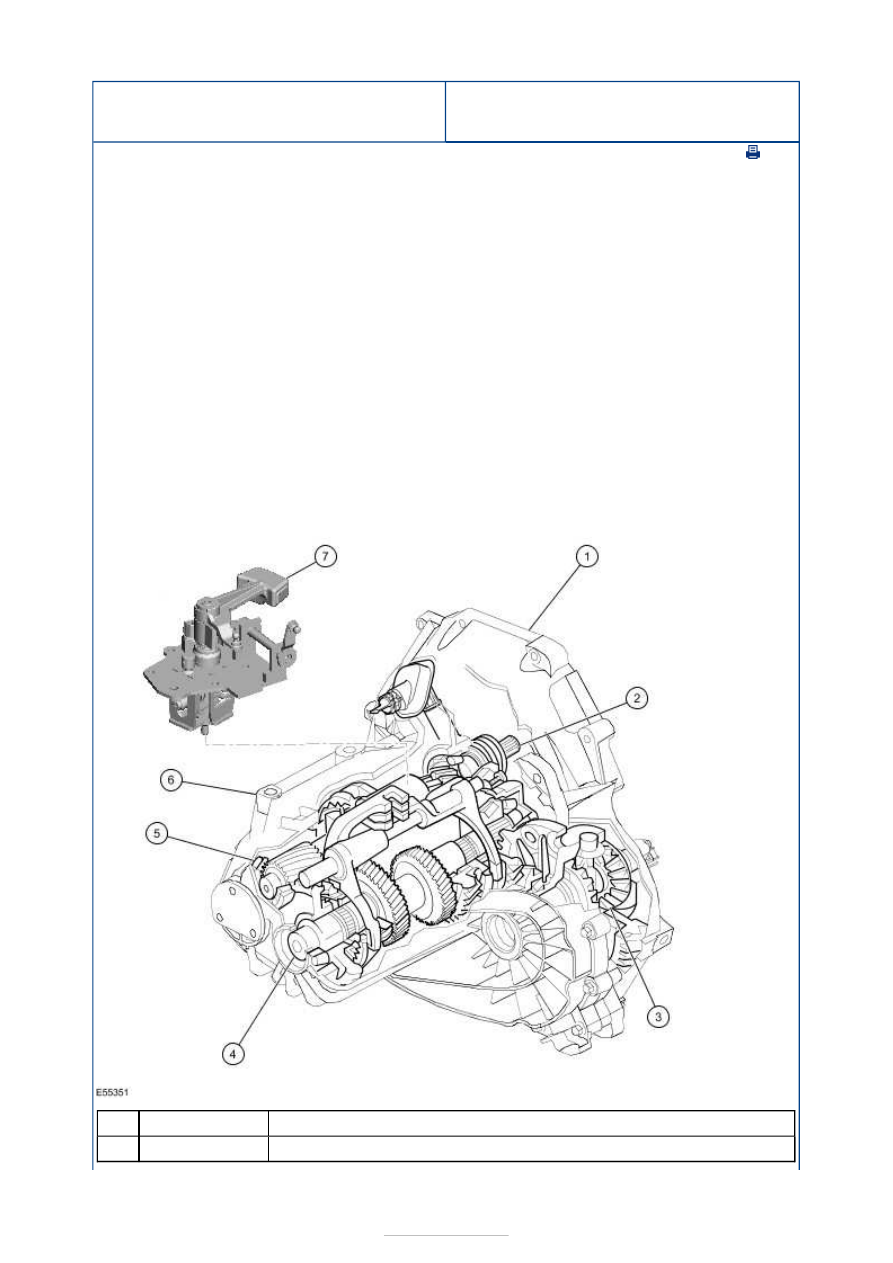
Overview 


Description 

Transaxle housing - clutch side 

Item

1


Part Number

-

-

Input shaft 

Differential assembly 

Output shaft 

Reverse gear idler 

Transaxle housing - transaxle side 

Selector mechanism 

Input and Output Shaft 


Description 

Reverse gear idler 

Reverse gear teeth 

Gear wheel - 5th gear 

Gear wheel - 4th gear 

3rd/4th gear synchroniser assembly 

Gear wheel - 3rd gear 

Teeth - 2nd gear 

Teeth - 1st gear 

Input shaft 

Output shaft 

Teeth - output shaft 

Gear wheel - 1st gear 

1st/2nd gear synchroniser assembly 

Gear wheel - 2nd gear 

Gear wheel - 3rd gear 

Gear wheel - 4th gear 

Gear wheel - 5th gear 

5th/reverse gear synchronizer assembly 

Gear wheel - reverse gear 

2

3

4

5

6

7

Item

1

2

3

4

5

6

7

8

9

10

11

12

13

14

15

16

17

18

19

-

-

-

-

-

-


Part Number

-

-

-

-

-

-

-

-

-

-

-

-

-

-

-

-

-

-

-

All gear wheels are constantly engaged. 

The output shaft teeth are part of the output shaft and are constantly engaged with the 
differential crown wheel. 

In the neutral position, none of the gear wheels is connected with the input or output shaft 
via the corresponding synchroniser assembly. No torque is transmitted to the differential. 

The input and output shafts are respectively mounted by means of tapered roller bearings 
in the halves of the transaxle housing on the clutch and transaxle sides. 

This bearing arrangement requires the shafts to be preloaded. 

The 3rd/4th gear synchroniser assembly is located on the input shaft. 

The 1st/2nd gear and 5th/reverse gear synchroniser assemblies are located on the output 
shaft. 

Power Flow 

1st gear 


Description 

Input shaft 

Output shaft 

Teeth - output shaft 

Gear wheel - 1st gear 

1st/2nd gear synchroniser assembly 

Teeth - 1st gear 

2nd gear 


Description 

Input shaft 

Output shaft 

Teeth - output shaft 

Item

1

2

3

4

5

6

Item

1

2

3


Part Number

-

-

-

-

-

-


Part Number

-

-

-

-

1st/2nd gear synchroniser assembly 

Gear wheel - 2nd gear 

Teeth (2nd gear) 

3rd gear 


Description 

Input shaft 

Output shaft 

Teeth - output shaft 

Gear wheel - 3rd gear 

3rd/4th gear synchroniser assembly 

Gear wheel - 3rd gear 

4th gear 


Description 

Input shaft 

Output shaft 

Teeth - output shaft 

Gear wheel - 4th gear 

Gear wheel - 4th gear 

3rd/4th gear synchroniser assembly 

5th gear 

4

5

6

Item

1

2

3

4

5

6

Item

1

2

3

4

5

6

-

-


Part Number

-

-

-

-

-

-


Part Number

-

-

-

-

-

-


Content   ..  509  510  511  512   ..