Ford Galaxy / Ford S-MAX. Manual - part 428
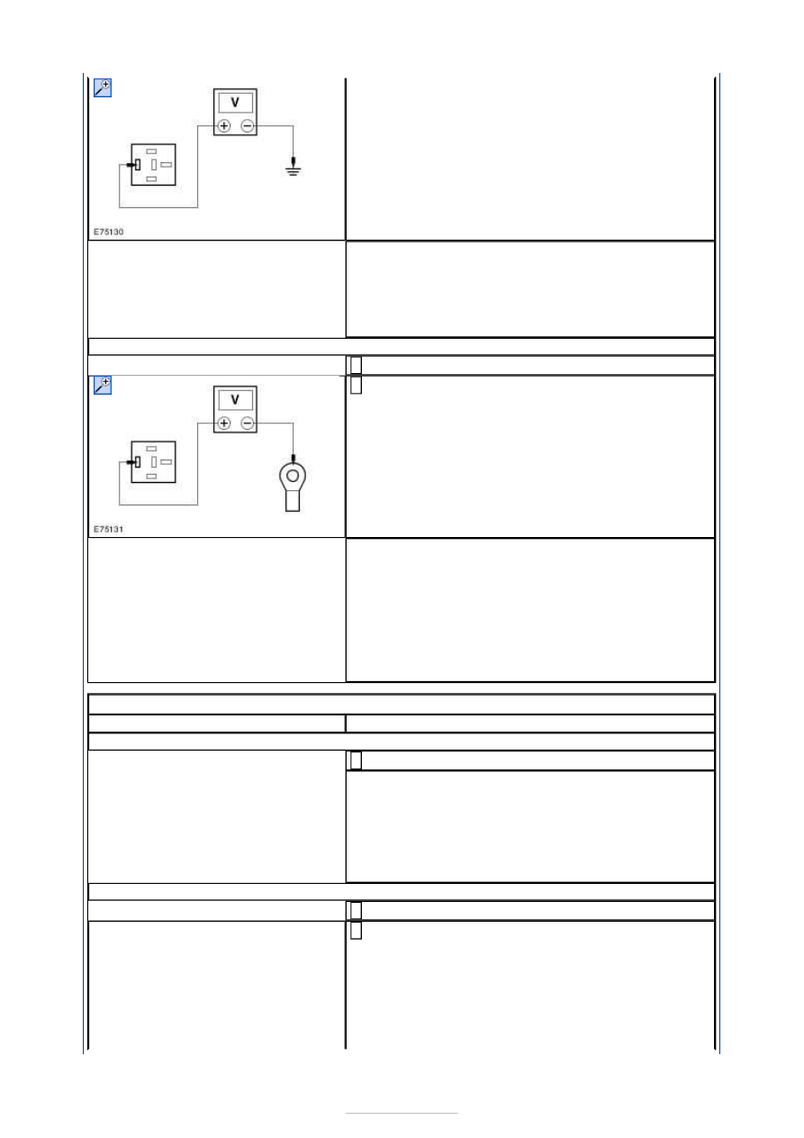
Is the voltage greater than 10 volts?
Yes
GO to B4
.
No
INSTALL a new BJB. TEST the system for normal
operation.
B4: CHECK CIRCUIT CDC35 (BU/WH) FOR CONTINUITY
Ignition switch in position 0.
1
Measure the resistance between the BJB starter
relay R1 connector pin 5 and the starter motor
solenoid C1DC35-B pin 1, circuit CDC35B (BU/WH).
2
Is the resistance less than 1 ohm?
Yes
INSTALL a new starter relay. TEST the system for
normal operation. If the concern persists, INSTALL
a new BJB. TEST the system for correct operation.
No
REPAIR circuit CDC35A (BU/WH) or circuit CDC35B
(BU/WH) as necessary. TEST the system for correct
operation.
PINPOINT TEST C : THE ENGINE CRANKS SLOWLY
TEST CONDITIONS
DETAILS/RESULTS/ACTIONS
C1: CHECK THE BATTERY VOLTAGE AND CONDITION
CHECK the battery using a battery tester.
1
Is the battery voltage and condition OK?
Yes
GO to C2
.
No
CHARGE or install a new battery as required.
CHECK the charging system using WDS. TEST the
system for normal operation.
C2: CHECK CIRCUIT SBF01A (RD) FOR VOLTAGE DROP
Ignition switch in position III.
1
Measure the voltage between starter motor
solenoid C1DC35-A-1 circuit SBF01A (RD),
component side and the battery positive terminal.
2