Ford Galaxy / Ford S-MAX. Manual - part 427
 

  Index      Ford     Ford Galaxy / Ford S-MAX - service repair manual 2006 year


Search            


Content   ..  425  426  427  428   ..


Ford Galaxy / Ford S-MAX. Manual - part 427


Pinpoint Tests 

NOTE: Use a digital multimeter for all electrical measurements. 

Starter Motor (303-06B Starting System - 2.5L Duratec-ST 
(VI5), Removal and Installation) /  
Starter Motor (303-06C Starting System - 1.8L Duratorq-
TDCi (Kent) Diesel, Removal and Installation) /  
Starter Motor (303-06D Starting System - 2.0L Duratorq-
TDCi (DW) Diesel, Removal and Installation). 
TEST the system for normal operation. 

PINPOINT TEST A : THE ENGINE DOES NOT CRANK AND THE RELAY DOES 
NOT CLICK 

TEST CONDITIONS

DETAILS/RESULTS/ACTIONS

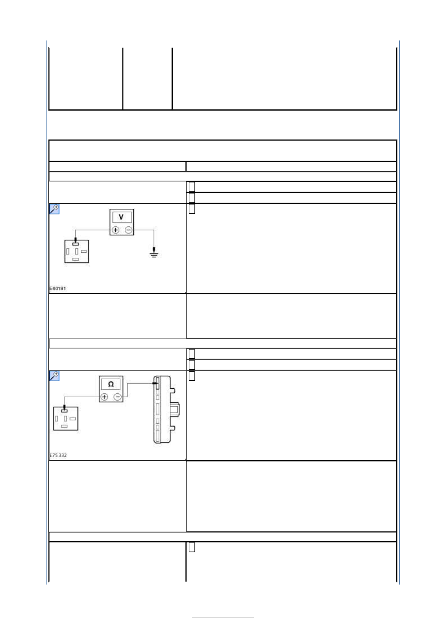
A1: CHECK THE STARTER RELAY COIL FOR VOLTAGE

Disconnect Starter Relay R1. 

Ignition switch in position III. 

Measure the voltage between the BJB starter relay 
R1 connector pin 1, circuit CDC35D (BU/WH), 

harness side and ground. 

Is the voltage greater than 10 volts? 
Yes 

GO to A3

.  

No 

GO to A2

.  

A2: CHECK CIRCUIT CDC35D (BU/WH) AND CDC35F (BU/WH) FOR CONTINUITY

Ignition switch in position 0. 

Disconnect Ignition Switch C2DC32. 

Measure the resistance between the BJB starter relay 
R1 connector pin 1, circuit CDC35D (BU/WH), 

harness side and the ignition switch C2DC32 pin 7, 
circuit CDC35F (BU/WH), harness side. 

Is the resistance less than 1 ohm? 
Yes 

INSTALL a new ignition switch. TEST the system for 
correct operation. 

No 

REPAIR circuit CDC35D (BU/WH) or circuit CDC35F 
(BU/WH) as necessary. TEST the system for normal 
operation. 

A3: CHECK THE STARTER RELAY COIL FOR GROUND

Measure the resistance between the BJB starter relay 
R1 connector pin 2, circuit CDC12A (YE), and 

ground. 


Is the resistance less than 1 ohm? 
Yes 

INSTALL a new starter relay. TEST the system for 
normal operation. 

No 

For vehicles with 1.8L Duratorq TDCi (Kent) Diesel 
and 2.0L Duratorq TDCi (DW) Diesel, 

GO to A4

.  

For vehicles with 2.0L Duratec HE (MI4), 

GO to A5

.  

For vehicles with 2.5L Duratec ST (VI5), 

GO to A6

.  

A4: CHECK CIRCUIT CDC12A (YE) FOR CONTINUITY

Ignition switch in position 0. 

Disconnect PCM C1E108-K. 

Measure the resistance between the BJB starter relay 
R1 connector pin 2, circuit CDC12A (YE) and the PCM 

C1E108-K pin K2, circuit CDC12A (YE), harness side. 

Is the resistance less than 1 ohm? 
Yes 

Using the WDS, CHECK for current DTCs. CORRECT 
all DTCs. TEST the system for normal operation. If 
the concern persists, INSTALL a new PCM. TEST the 
system for normal operation. 

No 

REPAIR the circuit. TEST the system for normal 
operation. If the concern persists, INSTALL a new 
BJB. TEST the system for normal operation. 

A5: CHECK CIRCUIT CDC12A (YE) FOR CONTINUITY

Ignition switch in position 0. 

Disconnect PCM C1E104-E. 

Measure the resistance between the BJB starter relay 
R1 connector pin 2, circuit CDC12A and the PCM 

C1E104-E pin L2, circuit CDC12A (YE), harness side. 

Is the resistance less than 1 ohm? 
Yes 

Using the WDS, CHECK for current DTCs. CORRECT 


all DTCs. TEST the system for normal operation. If 
the concern persists, INSTALL a new PCM. TEST the 
system for normal operation. 

No 

REPAIR the circuit. TEST the system for normal 
operation. If the concern persists, INSTALL a new 
BJB. TEST the system for normal operation. 

A6: CHECK CIRCUIT CDC35G (BU/WH) FOR CONTINUITY

Ignition switch in position 0. 

Disconnect PCM C1E108-B. 

Measure the resistance between the BJB starter relay 
R1 connector pin 1, circuit CDC35G (BU/WH), 

harness side and the PCM C1E108-B pin 17, circuit 
CDC35G (BU/WH), harness side. 

Is the resistance less than 1 ohm? 
Yes 

GO to A7

.  

No 

REPAIR circuit CDC35G (BU/WH). TEST the system 
for normal operation. If the concern persists, 
INSTALL a new BJB. TEST the system for normal 
operation. 

A7: CHECK CIRCUIT CDC12A (YE) FOR CONTINUITY

Disconnect BJB C1E108-B. 

Measure the resistance between the BJB starter relay 
R1 connector pin 2, circuit CDC12A (YE), harness 

side and the PCM C1E108-B pin 9, circuit CDC12A 
(YE), harness side. 

Is the resistance less than 1 ohm? 
Yes 

Using the WDS, CHECK for current DTC's. CORRECT 
all DTC's. TEST the system for normal operation. If 
the concern persists, INSTALL a new PCM. TEST the 
system for normal operation. 

No 

REPAIR circuit CDC12A (YE). TEST the system for 
normal operation. If the concern persists, INSTALL a 
new BJB. TEST the system for normal operation. 

PINPOINT TEST B : THE ENGINE DOES NOT CRANK BUT THE RELAY CLICKS 

TEST CONDITIONS

DETAILS/RESULTS/ACTIONS

B1: CHECK CIRCUIT CDC35B (GN/RD) FOR VOLTAGE

Ignition switch in position III. 

Measure the voltage between the starter motor 
solenoid C1DC35-B-1 circuit CDC35B (GN/RD), 

component side and ground. 


Is the voltage greater than 10 volts? 
Yes 

GO to B2

.  

No 

GO to B3

.  

B2: CHECK CIRCUIT SBF01A (RD) FOR VOLTAGE DROP

Ignition switch in position III. 

Measure the voltage between starter motor 
solenoid C1DC35-A-1 circuit SBF01A (RD), 

component side and the battery positive terminal. 

Is the voltage less than 2 volts? 
Yes 

CLEAN and TIGHTEN all battery positive cable 
connections. TEST the system for normal operation. 
If the concern persists, INSTALL a new starter 
motor.  
REFER to: 

Starter Motor

 (303-06A Starting System 

- 2.0L Duratec-HE (107kW/145PS) - MI4/2.0L 
Duratec-HE Flex Fuel (107kW/145PS) - MI4/2.3L 
Duratec-HE (118kW/160PS) - MI4, Removal and 
Installation) /  
Starter Motor (303-06B Starting System - 2.5L 
Duratec-ST (VI5), Removal and Installation) /  
Starter Motor (303-06C Starting System - 1.8L 
Duratorq-TDCi (Kent) Diesel, Removal and 
Installation) /  
Starter Motor (303-06D Starting System - 2.0L 
Duratorq-TDCi (DW) Diesel, Removal and 
Installation). 
TEST the system for normal operation. 

No 

CLEAN and TIGHTEN all battery positive cables 
connections. TEST the system for normal operation. 
If the concern persists, INSTALL a new battery to 
starter motor solenoid cable. TEST the system for 
normal operation. 

B3: CHECK THE STARTER RELAY CONTACT CIRCUIT FOR VOLTAGE

Disconnect Starter Relay R1. 

Measure the voltage between the BJB starter relay 
R1 connector pin 3 and ground. 


Content   ..  425  426  427  428   ..