Ford Galaxy / Ford S-MAX. Manual - part 380
 

  Index      Ford     Ford Galaxy / Ford S-MAX - service repair manual 2006 year


Search            


Content   ..  378  379  380  381   ..


Ford Galaxy / Ford S-MAX. Manual - part 380


The fuel pump has three pump elements, each offset from each other by 120 degrees. 

The fuel transfer pump is incorporated into the fuel pump and is located on the drive 
flange. The fuel transfer pump is a vane type pump. 

The fuel metering valve is located in the feed port between the high-pressure pump 
elements and the fuel transfer pump. It is controlled by the PCM using pulse width 
modulation. 

The high-pressure outlets of the three high-pressure pump elements are grouped together 
in a high-pressure connection. 

The fuel pressure regulator is located on the high-pressure outlet to the fuel rail. The fuel 
pressure regulator operates electromagnetically and is actuated by the PCM. 

Fuel rail 


Description 

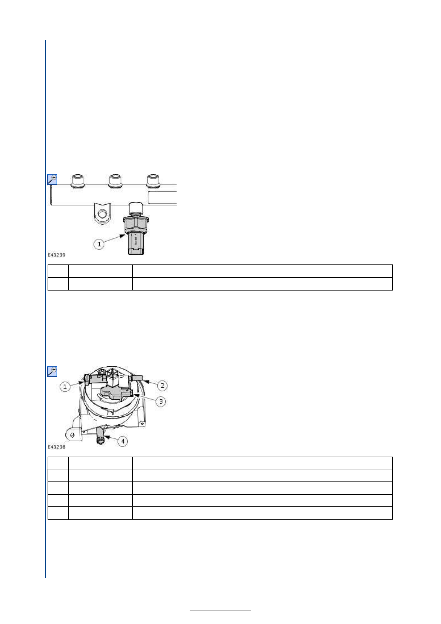
Fuel rail pressure (FRP) sensor 

The fuel rail is made from forged steel and is attached directly to the cylinder block. 

The high-pressure fuel is delivered through one high-pressure fuel supply line from the fuel 
pump to the fuel rail. 

From the fuel rail, the high-pressure fuel is directed to four more high-pressure fuel supply 
lines for fuel injection delivery by the fuel injectors. 

Fuel filter 


Description 

Fuel filter fuel supply union 

Fuel pump fuel supply union 

Electric fuel heater 

Drain plug 

The fuel filter is located above the fuel rail and is attached to the cylinder head by means of 
a bracket. 

The fuel filter has an electric fuel heater which is located centrally on the fuel filter between 
the supply connection and the drain connection. 

The fuel filter forms a single component with the housing and can only be renewed as a 

Item

1

Item

1

2

3

4


Part Number

-


Part Number

-

-

-

-

complete unit. 

The fuel filter also has a drain plug. This must be drained regularly in accordance with 
maintenance instructions. 

Fuel injectors 


Description 

High-pressure fuel supply union 

Electrical connector 

Fuel injector clamp 

Copper sealing washer 

Plastic guide bush 

Fuel injector fuel return port 

The fuel injectors are located centrally on the cylinder head upper section and are attached 
by means of clamps. 

The guide bushes in the cylinder head lower section and the plastic guide bushes on the 
fuel injectors make sure that they are centred properly. 

The fuel injectors are sealed off from the combustion chamber by means of a copper 
sealing washer located between the fuel injector and the cylinder head. A new sealing 
washer must be installed when servicing the fuel injectors. 

The fuel return lines are attached to the top of the fuel injector and are connected in series. 

Intake air shutoff throttle 

Item

1

2

3

4

5

6


Part Number

-

-

-

-

-

-


Description 

Manifold absolute pressure (MAP) sensor 

Intake air temperature (IAT) sensor 

Intake air shutoff throttle 

The intake air shutoff throttle is located on the intake air side of the intake manifold. 

The intake air shutoff throttle is electronically controlled by the PCM and is used to control 
vehicle characteristics while the engine is switched off. This will also prevent the engine 
being continuously fuelled by the engine oil after the ignition key has been turned to 
position 0. This is achieved by reducing the intake air through the intake manifold. 

Item

1

2

3

Part Number

-

-

-

Fuel Charging and Controls - 2.0L 
Duratorq-TDCi (85kW/115PS) - DW/2.0L 
Duratorq-TDCi (100kW/136PS) - 
DW/2.0L Duratorq-TDCi (103kW/140PS) 
- DW, Emission Requirements: Stage IV - 
Fuel Charging and Controls

S-MAX/Galaxy 2006.5 (02/2006-)


Print


Diagnosis and Testing 

General Equipment 

Principles of Operation 

The 2.0L DW10 engine uses a second generation Siemens common rail fuel injection 
system. The systems main components consist of a fuel pump, fuel rail, electrically 
operated fuel injectors, a fuel temperature sensor and a fuel rail pressure sensor. 

Fuel Pump 


Description 

Fuel pump fuel intake 

Fuel pump high-pressure fuel outlet 

Fuel metering valve 

High-pressure fuel pump chamber 

Fuel pump fuel return outlet 

High pressure fuel control valve 

The fuel pump consists of a transfer pump and a high-pressure fuel delivery pump. The 
transfer pump draws fuel from the fuel tank through the fuel filter and delivers the fuel to 
the three high-pressure fuel pump chambers through a fuel metering valve. The fuel 
metering valve controls the quantity of fuel that is allowed to enter the high-pressure fuel 
pump chambers. Excess fuel volume developed by the transfer pump is returned to the fuel 
tank. The fuel metering valve is controlled by the powertrain control module (PCM) using a 
pulse-width modulated signal. The high-pressure fuel pump outlet pressure is controlled by 
an electronic fuel control valve which is also controlled by the PCM.  

Fuel Rail 

Worldwide Diagnostic System (WDS)

Item

1

2

3

4

5

6


Part Number

-

-

-

-

-

-


Content   ..  378  379  380  381   ..