Ford Galaxy / Ford S-MAX. Manual - part 369
 

  Index      Ford     Ford Galaxy / Ford S-MAX - service repair manual 2006 year


Search            


Content   ..  367  368  369  370   ..


Ford Galaxy / Ford S-MAX. Manual - part 369


Fuel Charging and Controls - 2.5L Duratec 
(162kW/220PS) - VI5 - Throttle Body

S-MAX/Galaxy 2006.5 (02/2006-)


Print


Removal and Installation 

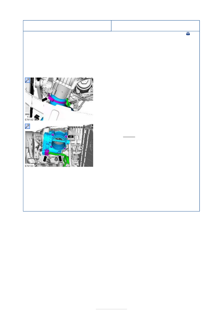
Removal 

NOTE: Removal steps in this procedure may contain installation details. 

Installation 

1. Remove the right-hand side headlamp assembly. 

Refer to: 

Headlamp Assembly

 (417-01 Exterior 

Lighting, Removal and Installation). 

2.  

3.

NOTE: The gasket is to be reused unless 
damaged. 

Torque: 

10 Nm 

1. To install, reverse the removal procedure. 

2.

NOTE: Make sure that the pedals remain in 
the rest position. 

Turn the ignition key to position II and wait for 
one minute to initialize the throttle body.  

3. Turn the ignition key to the OFF position. 


Fuel Charging and Controls - 1.8L 
Duratorq-TDCi (74kW/100PS) - 
Lynx/1.8L Duratorq-TDCi (92kW/125PS) 
- Lynx - Specifications

S-MAX/Galaxy 2006.5 (02/2006-)


Print


Torque Specifications 

a) Refer to the relevant procedure in this section. 

Description

Nm

lb-ft

lb-in

Fuel injector clamp retaining bolt

a

-

Fuel injection supply manifold retaining bolts

28

21

Fuel pump shield lower retaining bolts

33

24

Fuel pump shield upper retaining bolt

8

71

Fuel pump shield to fuel pump support bracket bolts

23

17

Fuel pump sprocket bolts

24

18

Fuel pump seal retaining nuts

10

89

Fuel pump pulley bolts

42

31

High-pressure fuel supply lines

40

30

Fuel pump retaining bolts

20

15

Charge air cooler intake pipe nut

9

80

Charge air cooler outlet pipe nut

9

80

Charge air cooler retaining bolts

5

44

Fuel metering valve retaining bolts

a

-

-

Fuel Charging and Controls - 1.8L 
Duratorq-TDCi (74kW/100PS) - 
Lynx/1.8L Duratorq-TDCi (92kW/125PS) 
- Lynx - Fuel Charging and Controls

S-MAX/Galaxy 2006.5 (02/2006-)


Print


Description and Operation 

Overview 


Description 

Fuel injector(s) 

Fuel rail pressure (FRP) sensor 

Fuel pressure regulator 

Fuel pump 

Fuel metering valve 

Fuel rail 

General 

A Siemens common rail fuel injection system is used on the 1.8L Duratorq-TDCi (Kent) 
diesel engine with stage 4 emission level (vehicle identification number (VIN) plate 
emission level code: S). 

Within the fuel pump there is an integral fuel transfer pump which draws the fuel from the 
fuel tank to the fuel pump. 

A fuel metering valve is located in the supply port to the high-pressure chamber of the fuel 
pump. The fuel metering valve varies the quantity of fuel supplied to the fuel rail and fuel 
injector(s), in relation to the driving conditions. 

The fuel is supplied at high-pressure to the fuel rail and to the fuel injectors ready for 
injection. Depending on engine operating conditions, the fuel injection pressure varies 
between 200 bar and 1600 bar. 

Fuel system pressure is measured using an FRP sensor located in the fuel rail. The FRP 
sensor converts the fuel system pressure into a voltage signal. This voltage signal acts as 
an input signal to the powertrain control module (PCM) for calculation of the fuel injection 

Item

1

2

3

4

5

6


Part Number

-

-

-

-

-

-

quantity. 

The PCM calculates the time of fuel injection and the fuel injection quantity depending on 
various input variables. 

The specified quantity of fuel is injected into the respective combustion chamber through 
the piezo-electrically actuated fuel injector(s). 

The excess fuel is returned to the fuel tank through the fuel return line. 

The fuel pressure regulator on the high-pressure outlet of the fuel pump regulates the fuel 
pressure in the fuel rail. 

Fuel pump 


Description 

Fuel pump fuel return port 

Fuel pressure regulator 

High-pressure fuel supply line port 

Fuel pump fuel supply port 

Fuel metering valve 

The fuel pump is driven clockwise at half the engine speed by the timing belt. 

The fuel pump has three pump elements, each offset from each other by 120 degrees. 

The fuel transfer pump is incorporated into the fuel pump and is located on the drive 
flange. The fuel transfer pump is a vane type pump. 

The fuel metering valve is actuated by the PCM using pulse width modulation. 

The fuel pressure regulator is located on the fuel pump. The fuel pressure regulator 
operates electromagnetically and is actuated by the PCM. 

Fuel rail 

Item

1

2

3

4

5


Part Number

-

-

-

-

-


Content   ..  367  368  369  370   ..