Ford Galaxy / Ford S-MAX. Manual - part 59
 

  Index      Ford     Ford Galaxy / Ford S-MAX - service repair manual 2006 year


Search            


Content   ..  57  58  59  60   ..


Ford Galaxy / Ford S-MAX. Manual - part 59


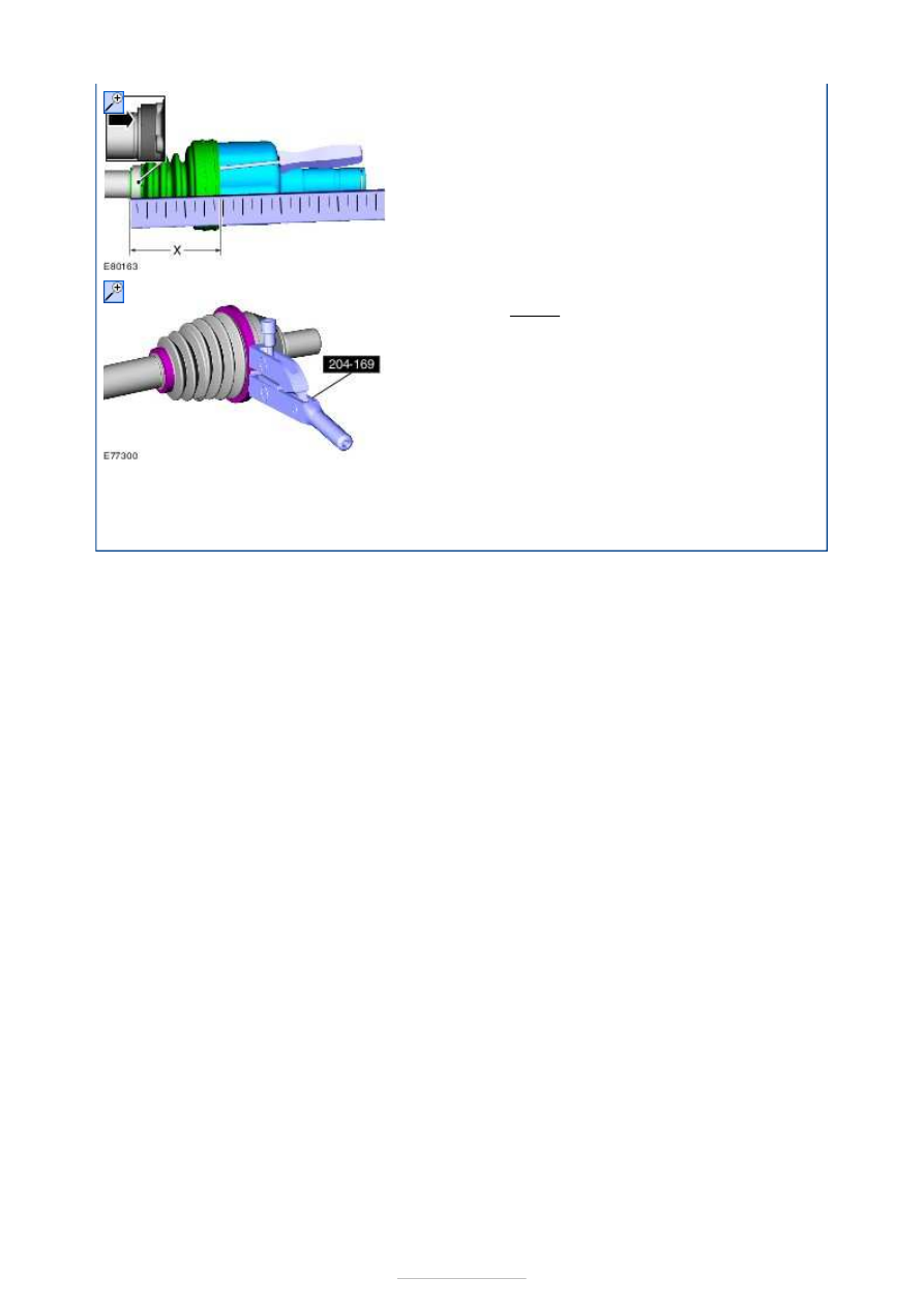
seat to allow the air to escape. 
Push on the tripode housing to stop, then 
pull it back 25 mm (x = 95 mm). 
Remove the screwdriver. 

6. Special Tool(s): 

204-169


Torque: 

21 Nm 

7. Refer to: 

Front Halfshaft LH

 (205-04 Front Drive 

Halfshafts, Removal and Installation). 
Refer to: 

Front Halfshaft RH

 (205-04 Front Drive 

Halfshafts, Removal and Installation). 


Front Drive Halfshafts - Outer Constant 
Velocity (CV) Joint Boot

S-MAX/Galaxy 2006.5 (02/2006-)


Print


Removal and Installation 

Special Tool(s) 

Removal 

Installation 

204-169 
Clamping Tool, Boot Retaining Clamp 

1. Remove the inner CV joint boot. 

Refer to: 

Inner Constant Velocity (CV) Joint Boot


(205-04 Front Drive Halfshafts, Removal and 
Installation). 

2.  

1.   

Fill the CV joint with grease. 
Insert a small screwdriver under the boot 
seat to allow the air to escape. 

2. Special Tool(s): 

204-169


Torque: 

21 Nm 

3. Install the inner CV joint boot. 

Refer to: 

Inner Constant Velocity (CV) Joint Boot


(205-04 Front Drive Halfshafts, Removal and 
Installation). 


Brake System - General Information - 
Brake System

S-MAX/Galaxy 2006.5 (02/2006-)


Print


Description and Operation 

The braking system is of a diagonally split, dual circuit design featuring front and rear disc 
brakes.  

The hydraulic system has separate circuits for each pair of diagonally opposed wheels (left 
front, right rear and right front, left rear). The front brake caliper is of a single sliding 
piston design which makes sure that equal effort is applied through both brake pads.  

The parking brake control operates the rear brakes through a cable system. There is also 
an electronic parking brake (EPB) system available.  

The brake master cylinder is of a tandem design and is linked to a brake booster which 
reduces the brake pedal effort. The tandem design will make sure that in the event of one 
brake circuit failing the other will remain fully operational.  

The brake booster vacuum on vehicles with diesel engine is provide by a camshaft driven 
vacuum pump.  

The anti-lock brake system (ABS) is controlled by the hydraulic control unit (HCU), 
incorporated within the hydraulic system, and only operates when the wheel speed sensors 
detect the onset of wheel lock up.  

Brake System - General Information - 
Brake System

S-MAX/Galaxy 2006.5 (02/2006-)


Print


Diagnosis and Testing 

Principles of Operation 

The brake system operates by transferring effort applied to the brake pedal by the driver to 
the brakes at each wheel. 

The braking effort is distributed to each wheel, using an hydraulic system. The system is 
assisted using a vacuum brake booster that reduces pedal effort and increases hydraulic 
pressure. The parking brake operates on the rear wheels and is applied using a hand 
operated control. 

Inspection and Verification 

1. 1. Verify the customer concern. 

2. 2. Visually inspect for obvious signs of mechanical damage. 

Visual Inspection Chart 

3. 3. If an obvious cause for an observed or reported concern is found, correct the cause 

(if possible) before proceeding to the next step. 

4. 4. If the concern is not visually evident, verify the symptom and refer to the 

Symptom Chart. 

Road Test 

Carry out a road test to compare actual vehicle braking performance with the performance 
standards expected by the driver. The ability of the test driver to make valid comparison 
and detect performance deficiencies will depend on experience. 

The driver should have a thorough knowledge of brake system operation and accepted 
general performance guidelines to make good comparisons and detect performance 
concerns. 

An experienced brake technician will always establish a route that will be used for all brake 
diagnosis road tests. The roads selected will be reasonably smooth and level. Gravel or 
bumpy roads are not suitable because the surface does not allow the tires to grip the road 
equally. Crowned roads should be avoided because of the large amount of weight shifted to 
the low set of wheels on this type of road. Once the route is established and consistently 
used, the road surface variable can be eliminated from the test results. 

Before a road test, obtain a complete description of the customer concerns or suspected 
condition. From the description, the technician's experience will allow the technician to 
match possible causes with symptoms. Certain components will be tagged as possible 
suspects while other will be eliminated by the evidence. More importantly, the customer 
description can reveal unsafe conditions which should be checked or corrected before the 
road test. The description will also help form the basic approach to the road test by 
narrowing the concern to specific components, vehicle speed or conditions. 

Mechanical

Tire pressure  
Wheels and tires  
Fluid leak from brake line(s)  
Fluid level  
Fluid contamination 


Content   ..  57  58  59  60   ..