Ford Galaxy / Ford S-MAX. Manual - part 54
 

  Index      Ford     Ford Galaxy / Ford S-MAX - service repair manual 2006 year


Search            


Content   ..  52  53  54  55   ..


Ford Galaxy / Ford S-MAX. Manual - part 54


Vehicle Dynamic Suspension - Vehicle 
Front Vertical Accelerometer

S-MAX/Galaxy 2006.5 (02/2006-)


Print


Removal and Installation 

Removal 

Installation 

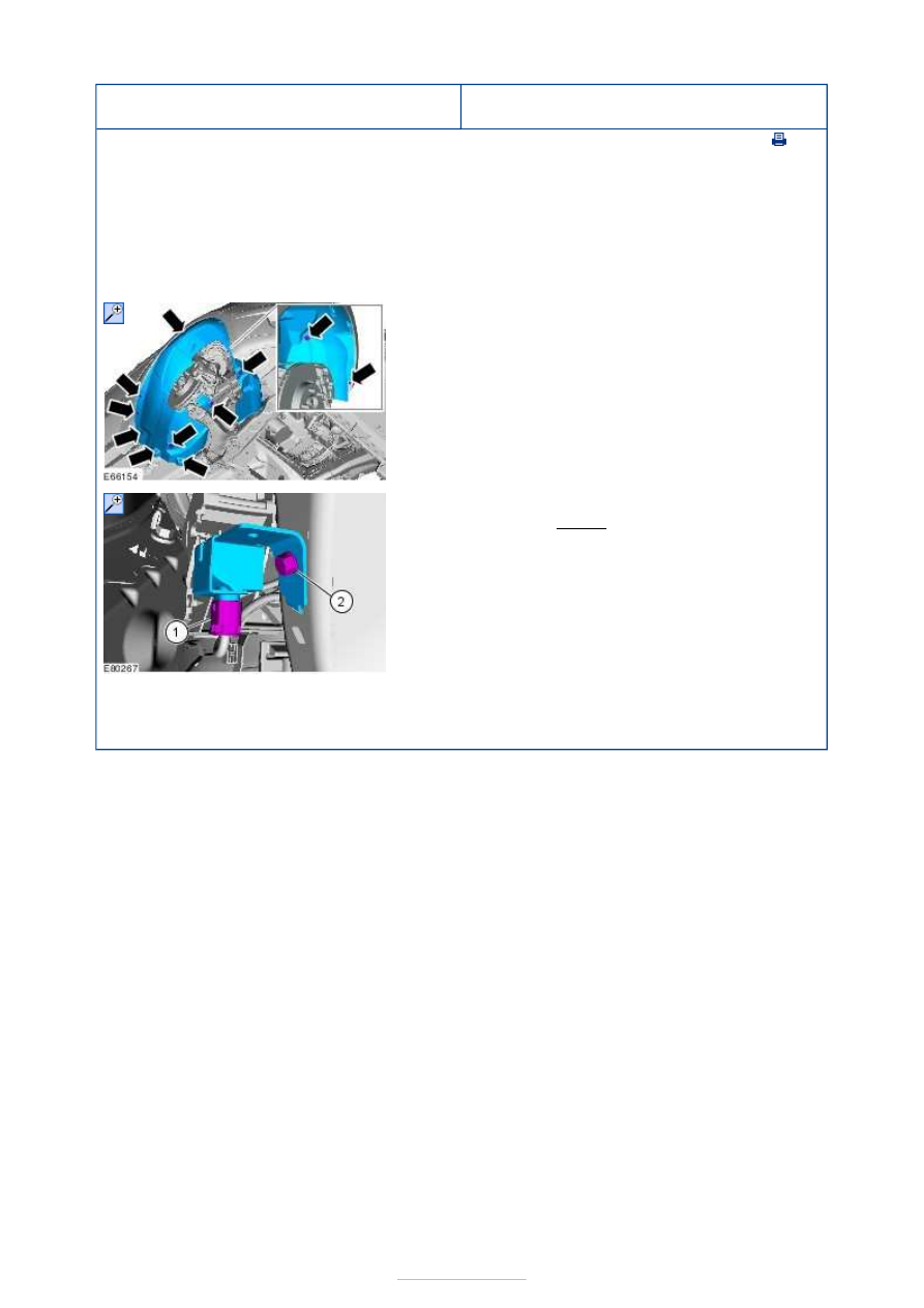
1. Remove the wheel and tire. 

Refer to: 

Wheel and Tire

 (204-04 Wheels and 

Tires, Removal and Installation). 

2.  

3.   

2. Torque: 10 Nm 

1. To install, reverse the removal procedure. 


Vehicle Dynamic Suspension - Vehicle 
Rear Vertical Accelerometer

S-MAX/Galaxy 2006.5 (02/2006-)


Print


Removal and Installation 

Removal 

Installation 

1. Remove the left-hand loadspace trim panel. 

Refer to: 

Loadspace Trim Panel - VIN Plate Body 

Style Code: S

 (501-05 Interior Trim and 

Ornamentation, Removal and Installation). 

2. Torque: 3 Nm 

1. To install, reverse the removal procedure. 


Front Drive Halfshafts - Specifications

S-MAX/Galaxy 2006.5 (02/2006-)


Print


Lubricants, Fluids, Sealers and Adhesives 

Capacity 

Torque Specifications 

Specifications

Outer Constant Velocity Joint Grease

WSS-M1C259-A1

Description

Driveshaft Joint Grease Fill Capacity

Inner (Grams)

Outer (Grams)

2.0L engine with manual transaxle

180

150

2.5L engine with manual transaxle

100

150

1.8L diesel engine with manual transaxle

180

150

2.0L diesel engine with manual transaxle

180

150

Item

Nm lb-ft lb-in

Intermediate shaft center bearing bracket to engine block bolts (M8)

25

18

-

Intermediate shaft center bearing bracket to engine block bolts (M10)

48

35

-

Front Drive Halfshafts - Front Drive 
Halfshafts

S-MAX/Galaxy 2006.5 (02/2006-)


Print


Description and Operation 

The halfshafts have constant velocity (CV) joints at both ends to provide smooth drive to 
the road wheels.  
The inner CV joints are sliding joints.  
The outer CV joints are fixed ball joints.  
The left-hand halfshaft CV joint is secured in the differential with a snap ring.  
The intermediate shaft (right-hand side) is secured in the differential by the intermediate 
shaft center bearing assembly.  
The outer CV joints are attached to the wheel hubs. 


Description 

Halfshaft LH 

Intermediate shaft center bearing assembly 

Halfshaft RH 

Authoring Template 

Working principle of the halfshafts 

The halfshafts transmit torque from the engine to the wheels.  
In order to allow vertical movement of the wheels and engine, the halfshafts operate at 
varying lengths and angles.  
The tripode joints allow for changes in halfshaft length during axial movements. 

Handling halfshafts 

CAUTION: The inner constant velocity (CV) joint must not be bent at more than 18 

degrees, the outer CV joint must not be bent at more than 45 degrees. 
NOTE: Do not place the tripode joint under tension. 

If removing/installing and disassembling/assembling the halfshafts, the following points 
should be observed: 

Item

1

2

3


Part Number

-

-

-


Content   ..  52  53  54  55   ..