Ford Ranger EV (2001 year). Manual - part 138
 

  Index      Ford     Ford Ranger EV - service repair manual 2001 year


Search            


Content   ..  136  137  138  139   ..


Ford Ranger EV (2001 year). Manual - part 138


414-03A-148

414-03A-148

High Voltage/Traction Battery

DISASSEMBLY AND ASSEMBLY (Continued)

Item

Description

Item

Description

9

High Voltage Four-Pin Auxiliary Load

1

Contactor Box 

Connector 

2

Two-Pin High-Voltage Connector 

10

High Voltage Four-Pin Auxiliary Load

3

Separator Plates 

Connector Bracket 

4

Traction Battery Case 

11

Contactor Box Harness 

5

Traction Battery Cooling Fan Relay 

12

High-Voltage (Sensor Lead) Harness

6

Traction Battery Cooling Fan 

(10B694) 

7

76-Pin Connector 

13

Low-Voltage Harness (10B691) 

8

Battery Control Module (BCM) 

14

Battery Module

(Continued)

Disassembly

1. Remove the traction battery. Refer to 

Traction

Battery

.

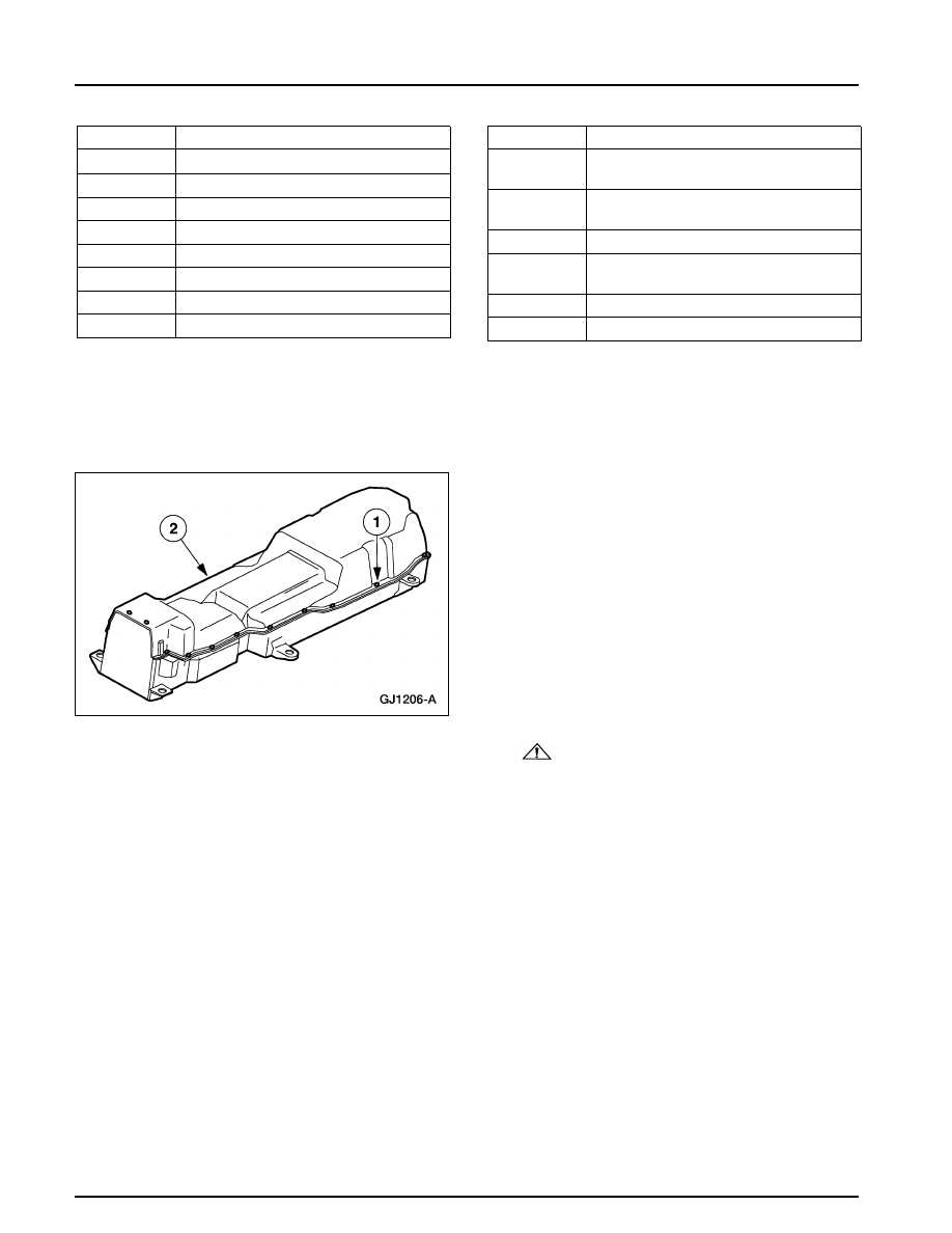
2. Remove the traction battery cover.

1 Remove the 22 bolts.
2 Remove the cover.

3.

WARNING: The nominal voltage of

the traction battery is 312 volts. The buffer
zone must be set up and insulated rubber
gloves and a face shield must be worn.
Failure to follow these precautions may
result in severe personal injury or  death. 
Observe the EV-specific precautions. Refer to 

Section 100-00

.

1 Set up the buffer zone.
2 Test and wear the insulated rubber gloves.
3 Wear the face shield.

414-03A-149

414-03A-149

High Voltage/Traction Battery

DISASSEMBLY AND ASSEMBLY (Continued)

4. Unclip the low and high-voltage wiring

harnesses from each other and from the
separator plate.

5. Unclip the low and high-voltage wiring

harnesses from each other and from the
separator plate.

Cut the zip tie.

6. Unclip the low and high-voltage wiring

harnesses from each other and from the
separator plate.

Cut the zip tie.

7. NOTE: There are 20 sense lead wiring

connectors. They can be identified by a white
tag with a black letter. 
Unclip and disconnect the sense lead wiring
connectors.

414-03A-150

414-03A-150

High Voltage/Traction Battery

DISASSEMBLY AND ASSEMBLY (Continued)

8. Unclip and disconnect the sense lead wiring.

9. Unclip and disconnect the sense lead wiring.

10. Unclip and disconnect the sense lead wiring.

11. Unclip and disconnect the sense lead wiring.

414-03A-151

414-03A-151

High Voltage/Traction Battery

DISASSEMBLY AND ASSEMBLY (Continued)

12. Unclip and disconnect the sense lead wiring.

13. Cut the two zip ties from the high-voltage

harness.

14. NOTE: The battery control module (BCM) is

held in position with strips of Velcro

TM

Remove the BCM.
1 Loosen the four bolts and disconnect the

four multi-pin connectors from the BCM.

2 Remove the BCM.

15. NOTE: The high-voltage harness is wrapped

with orange tape and runs from the contactor
box to the BCM. 
Remove the high-voltage harness.


Content   ..  136  137  138  139   ..