Ford Ranger EV (2001 year). Manual - part 134
 

  Index      Ford     Ford Ranger EV - service repair manual 2001 year


Search            


Content   ..  132  133  134  135   ..


Ford Ranger EV (2001 year). Manual - part 134


414-03A-132

414-03A-132

High Voltage/Traction Battery

REMOVAL AND INSTALLATION (Continued)

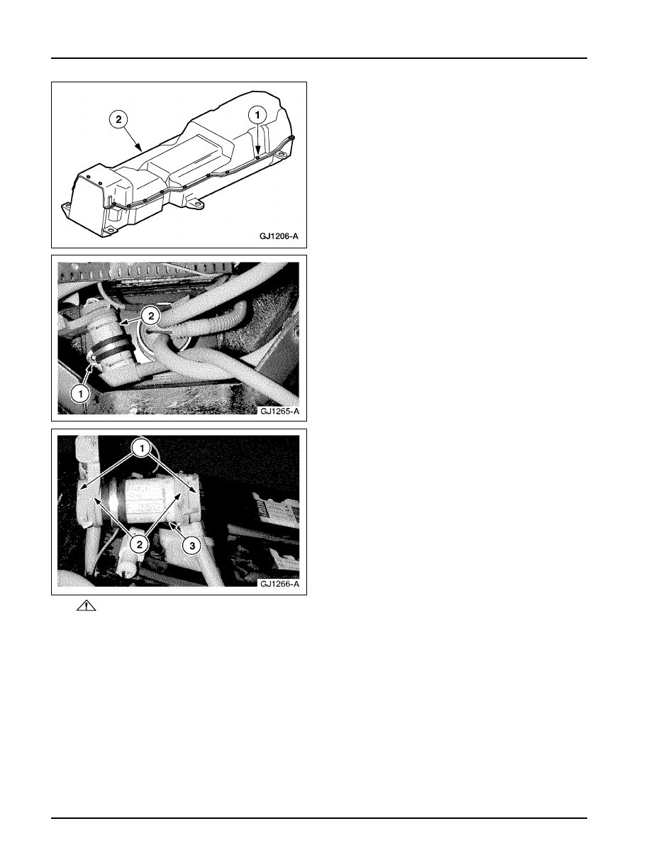
3. Remove the traction battery cover.

1 Remove the 22 bolts.
2 Remove the cover.

4. Position the high-voltage fuse aside.

1 Remove the nut.
2 Move the fuse up and out of the traction

battery pack.

5.

WARNING: Do not allow the HVJs to

touch each other once they are removed
from the high-voltage fuse. The HVJs contain
high DC voltage and may cause severe
personal injury or death. 
Remove the high-voltage fuse.
1 Use the Battery Terminal Cap Opener to

open the battery module caps.

2 Remove the two bolts.
3 Remove the fuse.

414-03A-133

414-03A-133

High Voltage/Traction Battery

REMOVAL AND INSTALLATION (Continued)

Installation

1. To install, reverse the removal procedure.

Fill the area around the high-voltage fuse
bolts with Nyogel.

Apply Locktite 242 to the 22 traction
battery cover bolts.

Traction Battery Module — Modules 1-7

Removal

1. The battery modules are located on the upper

level of the traction battery. Replace the faulty
battery module(s). Refer to 

Traction Battery

Module Replacement

.

414-03A-134

414-03A-134

High Voltage/Traction Battery

REMOVAL AND INSTALLATION (Continued)

Installation

1. The battery module replacement procedure also

contains the battery module installation.

Traction Battery Module — Modules 17-18

Removal

1. These two battery modules are located in the

upper level near the front of the traction
battery. Replace the faulty battery module(s).
Refer to 

Battery Control Module (BCM)

.

Installation

1. The battery module replacement procedure also

contains the battery module installation.

Traction Battery Module — Modules 19-21

Removal

1. Remove the battery control module (BCM).

Refer to Battery Control Module (BCM).

2. Replace the faulty battery module(s). Refer to

Traction Battery Module Replacement

.

Installation

1. The battery module replacement procedure also

contains the battery module installation.

2. Install the (BCM). Refer to 

Battery Control

Module (BCM)

.

414-03A-135

414-03A-135

High Voltage/Traction Battery

REMOVAL AND INSTALLATION (Continued)

Traction Battery Module — Modules 8-11

Special Tool(s)

Battery Module Lifting Tool

SR-10009

Battery Post Torque Wrench

307-026

Removal

1.

WARNING: The nominal voltage of

the traction battery is 312 volts. The buffer
zone must be set up and insulated rubber
gloves and a face shield must be worn.
Failure to follow these precautions may
result in severe personal injury or  death. 
Observe the EV-specific precautions. Refer to 

Section 100-00

.

1 Set up the buffer zone.
2 Test and wear the insulated rubber gloves.
3 Wear the face shield.

2. Remove battery modules 4-6.

Unclip and disconnect the heating element
electrical connectors.

Remove the separator plates.

Remove and discard the high-voltage jumper
retaining nuts.

Use the Battery Module Lifting Tool to
remove the battery modules.

3. Replace the faulty battery module(s). Refer to

Traction Battery Module Replacement

.


Content   ..  132  133  134  135   ..