Ford Ranger EV (2001 year). Manual - part 128
 

  Index      Ford     Ford Ranger EV - service repair manual 2001 year


Search            


Content   ..  126  127  128  129   ..


Ford Ranger EV (2001 year). Manual - part 128


414-03A-108

414-03A-108

High Voltage/Traction Battery

REMOVAL AND INSTALLATION (Continued)

3.

WARNING: The nominal voltage of

the traction battery is 312 volts. The buffer
zone must be set up and insulated rubber
gloves and a face shield must be worn.
Failure to follow these precautions may
result in severe personal injury or  death. 
Observe the EV-specific precautions. Refer to 

Section 100-00

.

1 Set up the buffer zone.
2 Test and wear the insulated rubber gloves.
3 Wear the face shield.

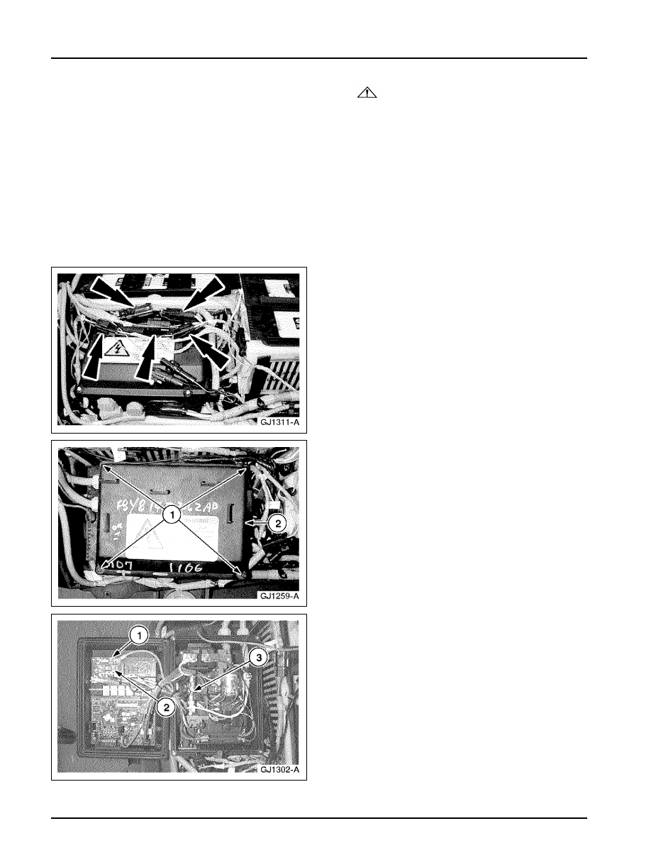
4. Pull the connectors from the top of the

contactor box.

5. Open the contactor box.

1 Remove the four screws.
2 Open the contactor box.

6. Use a fuse puller to remove the necessary fuse.

1 25A Charger Fuse
2 10A Heater Fuse
3 40A Auxiliary Fuse

414-03A-109

414-03A-109

High Voltage/Traction Battery

REMOVAL AND INSTALLATION (Continued)

Installation

1. To install, reverse the removal procedure.

Apply Locktite 242 to the 22 traction
battery cover bolts.

HVPDB Fuses

Removal

1. Disconnect the traction battery auxiliary load

high-voltage connector. Refer to 

 Section

100-05

.

2. Remove the high-voltage power distribution box

(HVPDB) cover.
1 Remove the four screws.
2 Remove the cover.

414-03A-110

414-03A-110

High Voltage/Traction Battery

REMOVAL AND INSTALLATION (Continued)

3. Remove the HVPDB fuse safety cover.

1 Remove the two screws.
2 Remove the cover.

4. Use a fuse puller to remove the necessary fuse.

1 10A Power Steering Fuse
2 25A Positive Temperature Coefficient (PTC)

Heater Fuse

3 25A A/C Fuse
4 10A DC/DC Fuse

Installation

1. To install, reverse the removal procedure.

414-03A-111

414-03A-111

High Voltage/Traction Battery

REMOVAL AND INSTALLATION (Continued)

High Voltage Power Distribution Box (HVPDB)

Removal

1. Remove the positive temperature coefficient

(PTC) module. Refer to 

 Section 412-04

.

2. Disconnect the power steering pump electrical

connector.

3. Disconnect the electrical connectors.


Content   ..  126  127  128  129   ..